A chinese PA for 6cm

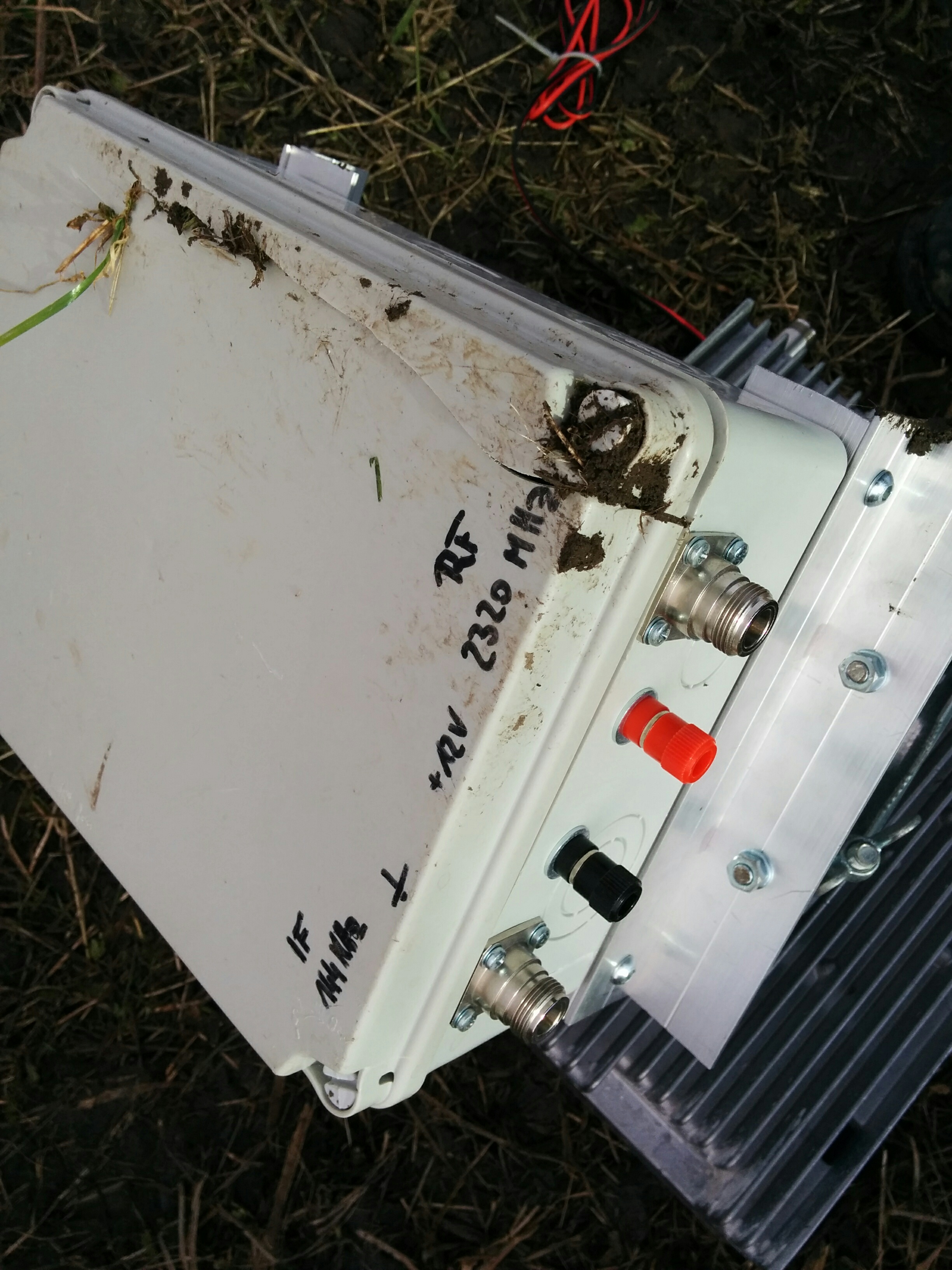
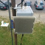
Some posts ago i wrote about my new 6cm transverter. I already did a few QSO and i got a 10W PA for a good price. Unfortunately this PA needs 1W of Input and the transverter gives maximum of 250mW output. So a small “driver” is needed. I was researching the options but found no easy solution that also fits my budget constraints. Then i saw some amplifiers sold as WLAN amp. Usually those are for 2.4GHz but i thought if there are some for the one band there are probably also some for the 5GHz band. During the search i found the nice Amp on the picture below that is sold as an amplifier for video transmissions for about 22Euro. It is specified with 3.5/4.5W. But whatever output power for the price i thought i cannot do wrong a lot.
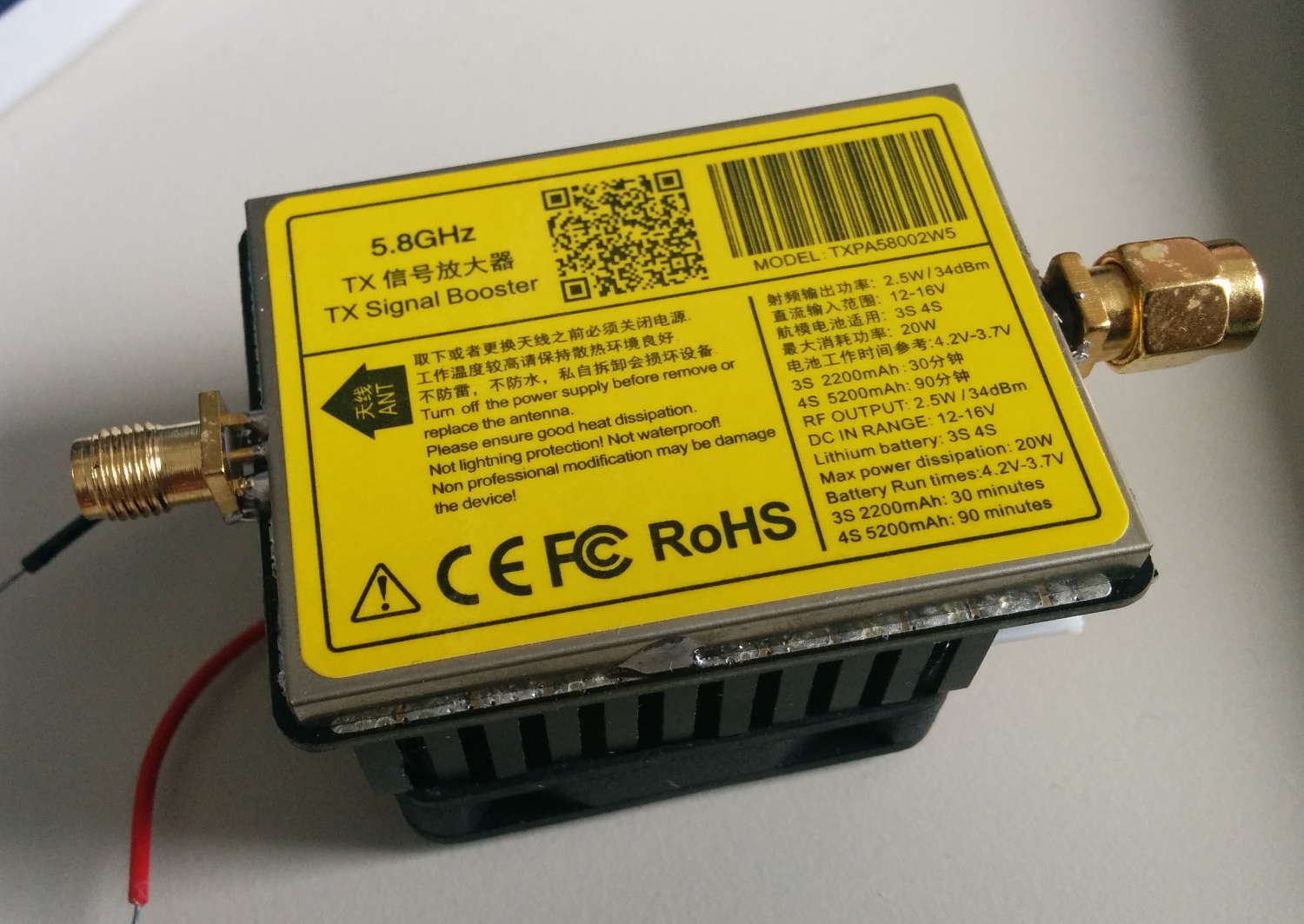
A chinese 5.8GHz PA

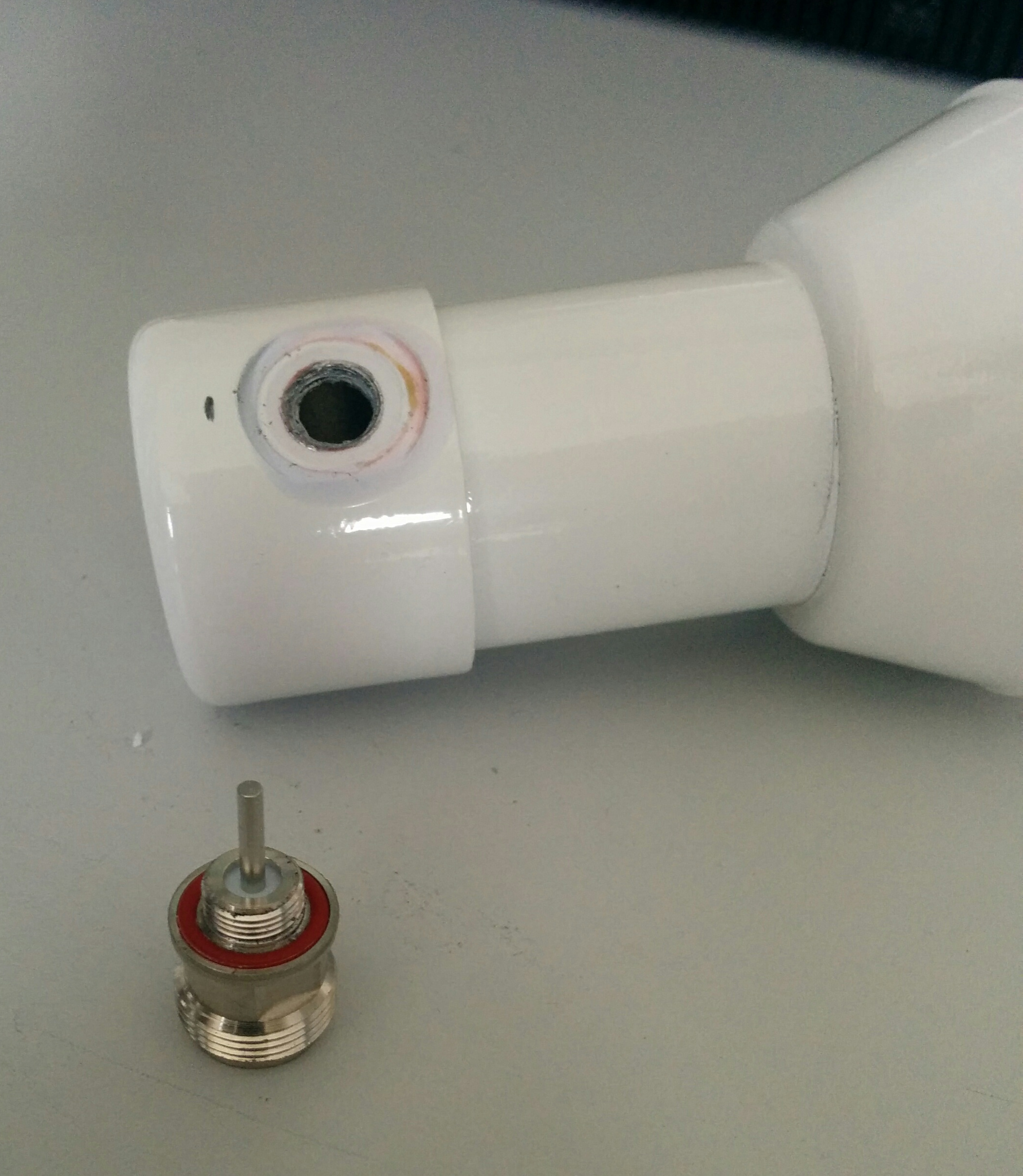
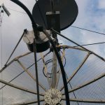
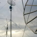
When the device arrived i had to find out the supply voltage. In fact it works with 12V and a first test confirmed it has some gain. The bad thing was that the connectors were reverse SMA and for each connector it was quite some gap between the connector and the PCB. So i thought, “thats a strange matching method” ;)
After removing the soldered shield on top of the PCB one of the screws for mounting the heatsink also came out.
The semiconductors used in the PA are 2x Skyworks SE5004L with a P1dB of 30dBm typical and 34dBm max. So i thought 2W should be possible at least. The gain is specified with 32dB. At the input of the PA is a pi-attenuator.
Later i soldered some nice SMA jacks and then the PA went to storage for quite some while.

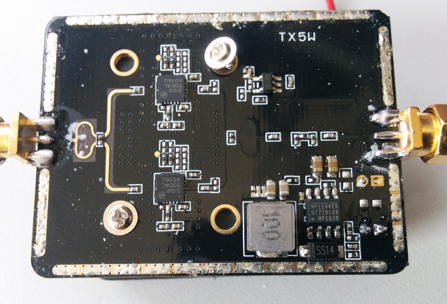
The “inner values” of the small amplifier

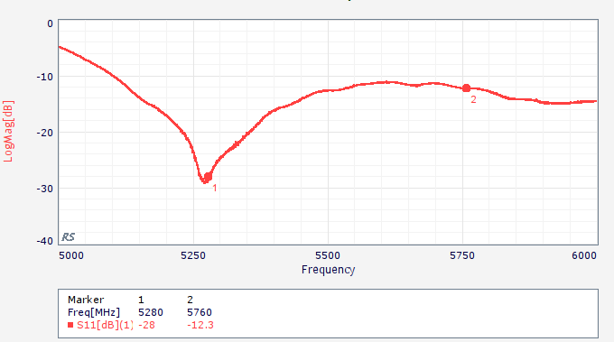
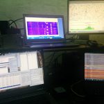
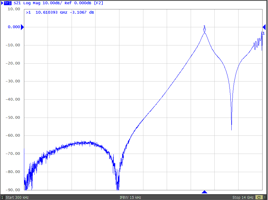
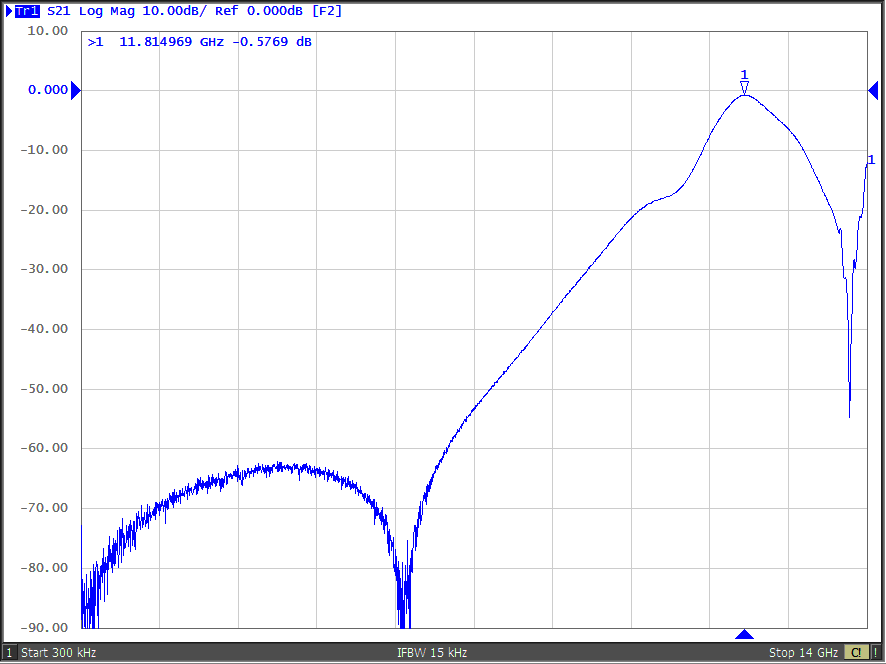
Now i found some minutes to remove the attenuator and do some raw measurement of the output power. The gain of the amplifier is about 28..29dB. I did not measure the cable attenuation exactly so do not nail me down on the last dB.
The input vs output figure you can find below. The P1dB is about 2.5W. So considering the samples to be typical there is quite some loss on the PCB. But even in that case for the given price its a nice thing.

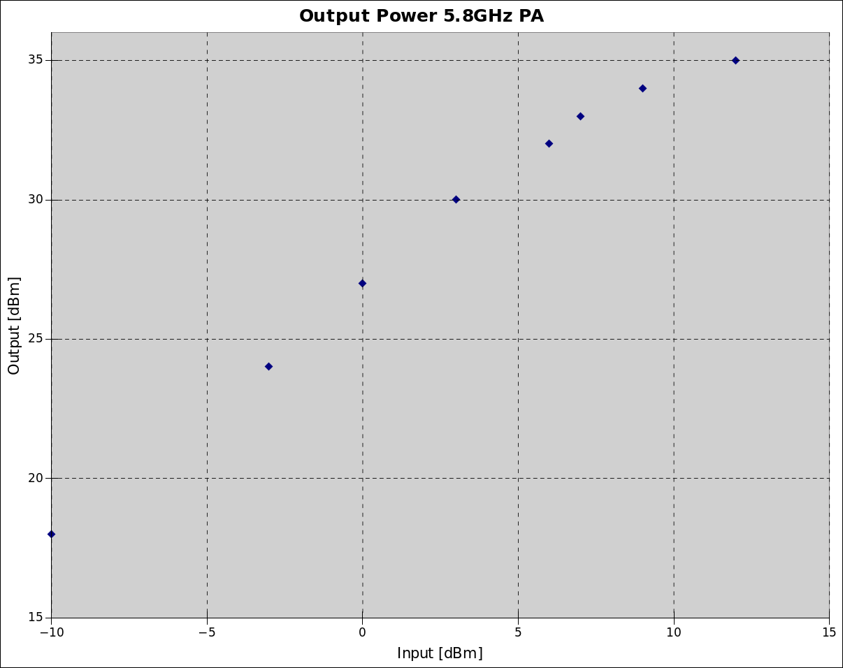
5.8GHz video PA output power

Almost a antenna feed for 6cm …

Not all things work out… I was searching for some nice feed for a offset dish to be used for 6cm narrow band. In the internet i found a nice version from Russia.
It was announced for the 5GHz WLAN band without dedicated specification of the exact frequency.
For 40 Euro including shipment it was ordered and after only 2 weeks in transit (russian saying tells: For bad children Santa Claus sends the gifts by russian post… ;) ) and 1 week in customs i finally got my russian present.

5GHz horn from Russia


Measuring the input matching shows that its well in the middle of the lowest 5GHz WLAN band.

WLAN horn matching measurement


Far away from 5760MHz. But ok, lets try. First i removed the N connector.

5GHz horn from Russia


The connector with the radiator seems to be a robust construction. I tried to shorten it step by step. Unfortunately it happened what could be expected. The feed can be de-tuned to about 5.5GHz but above that the matching vanishes. Probably the distance to the backside of the horn is too big. So this one was a fail. Fortunately i can still use it for WLAN if i make the radiator a bit longer again. If you want to use the lowest of the 5GHz bands it is really a nice and very solid construction.

June DUR from JO54LJ

This year i was on vacation again during the June DUR weekend.
So i took the 23cm transverter + FT-817 + my 16ele Yagi with me to do some aircraft scatter QSO.
My location was balcony on the 8th floor but with decent takeoff towards JO60/61. Takeoff more towards west was slightly better.
Looking to the Airscout software revealed very few planes. This resulted in weak and very short reflections. In the end 3 QSO. Best signal was from DJ5AR this time which was the most distant QSO.
Unfortunately i found no other station for a QSO in the north.

Antenna mounted to rainfall pipe. Baltic sea in the background.

my portable station. You can see the arm of my 3year old co-op “operating” the chat PC ;)

China LNA

I was searching for some simple LNA for microwave reception and found a very cheap board from China. For less than 10 Euro i ordered a LNA board that is specified to work from 50MHz to 6GHz. The gain should be about 20dB at 50MHz and still >10dB at 6GHz. Even if it does not work like that the PCB with shield and SMA jacks is still a good deal. You can find some measurement results below. The original condition makes clear that the gain on the upper frequencies is not good. Touching the bias network with the finger showed slight improvements. So it was clear that there is some problem with the components feeding the MMIC. Exchanging the ferrite bead by a 68nH RF coil gives much better results up to 4.5GHz but still has problems on the highest frequencies. So i tried a 2.7nH i series directly connected to the RF trace in order to avoid the stub that was there before. Now 6GHz is good but there is a resonance at about 3.5GHz. My last attempt was an additional 120nF to ground between the two coils. Thats pretty promising for the microwave bands but below 800MHz the LNA is not usable anymore. So the network still has room for improvement but it is at least clear that the board is usable.

Chinese LNA with german finger ;)

measurement results for different bias networks

DUR1702 @JO61XA

I was not qrv from JO61XA for a long time. Now there was the chance to take all the equipment to Triebenberg again. During the last months i tried to repair some things here and there. The 9cm transverter got a new alignment and is working now. Saturday morning i collected all the stuff and partly assembled it. I wanted to go for 23/13/9cm and 3cm eventually. This time i used the 1m dish that i bought last year in order to save some time during the mast construction. In the end i was qrv 1 hour after beginning of the activity. So what… The goal is to test the hardware. First observations were not that promising: 1) bad connection of the DC supply for the mast transverters 2) control unit for the rotator was not working.

The later one was really bad. Later at home i noticed that i partly disconnected the cable for the display / keypad unit when fixing some loose screws few weeks ago.

For 3cm i picked a second IF transceiver. Unfortunately the wrong one. The IF is 432MHz but i took the FT-290 instead the 790R2 ;) RX/TX switching via the mimic for the 2m based transverters from the FT-817 was not working but it took me almost until end of the test to find out what was going on. So only 1 QSO there.

Also 23cm seemed to have some oscillation in the RX LNA. I got some very strange sounds from time to time when releasing the PTT. Maybe some feedback from the 13/9cm transverters because of the PTT mimic i use (i switch all chains to TX but only transfer the IF to the one i want to use. Decoupling is only 50dB which might be an issue. I need to investigate there).

Finally, when deconstructing the mast, i was a bit optimistic on the way to remove the ropes and had a very robust takedown of the antenna and transverters. The main impulse was taken bei the box of the 13cm transverter. Fortunately only the plastic box splitted into several segments. The transverters are still working fine… lucky operator ;) I anyway want to put it into a common box with the 6cm i am going to build and the new 9cm i have flying around as components here.

Hope to hear you again next time.

damaged 13cm transverter box


GPS 10MHz reference

Since some time i own a DF9NP GPSDO. Currently i only use it to lock my signal generator but i also want to use it for my microwave transverter OCXOs. When connecting a SMIQ signal generator and checking the signal output at 6GHz i noticed some +-50Hz jitter under the poor reception conditions at thelocation of this signal generator. So i want to look a bit closer into that topic. In China i ordered a Neo-M8N module that can be configured to provide a 10MHz clock at its timepulse output. I tried to compare it with the GPSDO and the OCXO of my SMY-02 signal generator.
Of cause the digital clock has significant jitter because it is generated by a CPU (specified with +-10ns).

Neo-M8N clock output at 10MHz

The picture of the timepulse at 10MHz shows, that it seems that comparing the clock to a stable oscillator over a relatively short period could be sufficient for adjusting the frequency of this oscillator to the GPS.

GPSDO, M8N, OCXO

The screenshot shows the oscilloscope triggered to the GPSDO (green). The output of the M8N module (yellow) shows the jitter and the adjustment range within 60 seconds (yellow shadow). The third (blue) trace comes from my SMY-02 which was locked to the GPSDO. The SMY signal shows some slight jitter compared to the reference. To me it is not clear if the cause is the reference or the locking in the generator. The clock from the M8N module shows significant adjustment of the clock frequency within the 60 seconds shown compared to the GPSDO which has a TCXO that is slowly compensated by the GPS inside the reference.
Looking to the signal in frequency domain shows this picture:

Neo M8N spectrum

There are rather close sidebands that require narrow band adjustment of a oscillator eventually locked to this GPS clock. Wideband the spectrum is noisy as well.

M8N phasenoise at 10MHz

Finally i took a short video showing the the scope triggered to the 10MHz OCXO reference of the SMY and comparing the GPSDO and the M8N output. The OCXO is slightly off 10MHz and therefore the picture is moving all the time. You can also see that the M8N is slowly adjusting compared to the GPSDO output.

GPS 10MHz GPSDO vs Neo-M8N and 10MHz OCXO

Attiny RX/TX sequencer

RX/TX Sequencer with Attiny

Sequencer for Transceiver and Transverter sequence control made around a Attiny2313. It can switch a RX/TX relais lowside, a PA supply highside, has “active” and a “TX inhibit” outputs. Furthermore there is a input to lock the PTT from a second sequencer (switch on the RX/TX relais only). There is an extra 7bit output driver that is in that example used to drive a pulse controlled RF relais.

Oktober 16 @ JO60OM

Antennas in October contest 2016

The weather in JO60OM was obviously quite good compared to other contest locations. A nice and warm Saturday, no rain during the night and sunny sky at Sunday morning. In afternoon it started raining and the rain continued until we were back home.
The equipment was running quite well. 13/9/6cm was operated by 2 operator new to microwave under the DN5TA training call. The 23cm operation was nice with ODX G3XDY about 860km. But i had the impression that the activity is declining each contest. You really need to push the people in chat in order to get QSO done. Between 0100UTC and 0400UTC even the chat activity almost stopped. The band was empty.

Here you can listen to the ODX QSO with G3XDY:

Some pictures:

23cm signals are very wideband sometimes

23cm signals are very wideband sometimes

6cm Pipecap filter [part 2]

I shortened the probe pins of my experimental pipecap filter to 5mm in order to get rid of the unwanted response around 7GHz. As expected the filter is rather narrow now and the attenuation increases a lot.
Marcel made some new measurements up to 14GHz in order to see how the suppression behaves. It looks a lot better now but you can also see that at the upper end of the measurement range the attenuation is very low (keep in mind that the probes are nice quarter wavelength antennas there).
The following picture shows the filter tuned to the 6cm band:

pipecap 5mm  probes 5760MHz

pipecap 5mm probes 5760MHz

The passband attenuation is now always somewhere in the range of 2..3dB.

Tuned to the upper end of the possible range you see that it behaves more than a lowpass than a bandpass ;) The passband gets a bit wider.

pipecap 5mm probes 10610MHz

pipecap 5mm probes 10610MHz

pipecap 5mm probes 11815MHz

pipecap 5mm probes 11815MHz

I would assume that it makes most sense to design the probes beeing quarter lambda for the frequency were the notch of the filter appears (or slightly above). Since this depends on the frequency you want to tune the filter to you need to consider that before you make the filter.

Pipecap filter dimensions

Pipecap filter dimensions