LNA with SPF5043 and SAW filter

A while ago i tried the Eagle import capabilities of Kicad. I used a design of the baloon experimenteer “TT7” from Czech Republic and did some modifications to the layout. Since the LNA looked promising i sent the design for production and ordered some components. I had to replace some components for easier sourcing.
The MMIC i replaced with the compatible type SPF5043. Instead of the 3.3V regulator i used the variant with 5V output and up to 16V input. The options for the SAW filters are limited. The 70cm filters usually allow for the lower half of the band but the curve will degrade around 437MHz. A filter for 23cm and one for 13cm was availabe as well. The same for 1090MHz. Unfortunately none for 405nm was available. There is an option for phantom feed of the LNA as well as mounting an ESD diode. Unfortunately i did not care about the width of the RF traces. They are far to wide. Fortunately the trace in front of the MMIC is short.
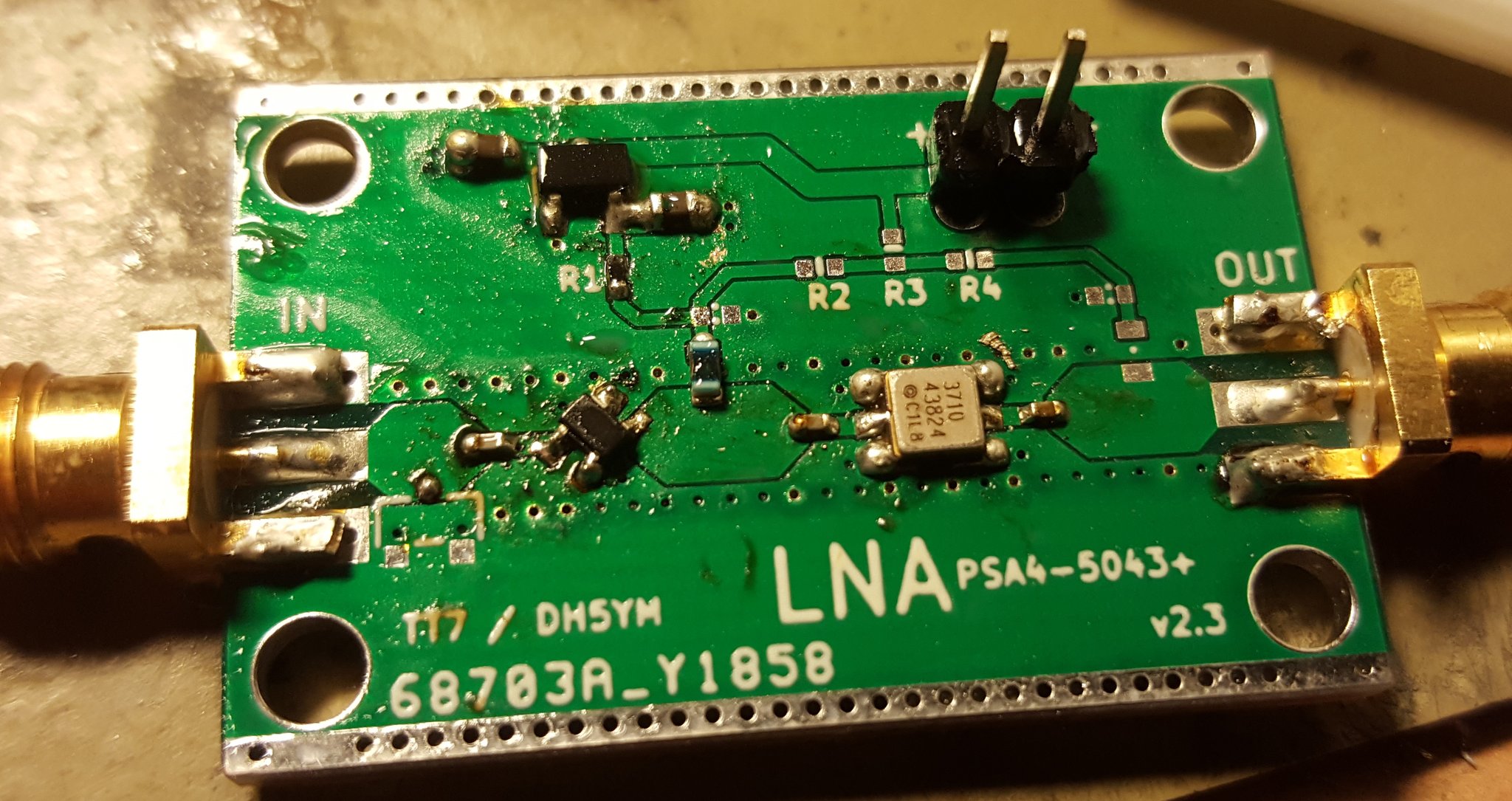
SAW filtered LNA


For test i assembled one board for 70cm, 23cm and 13cm each.
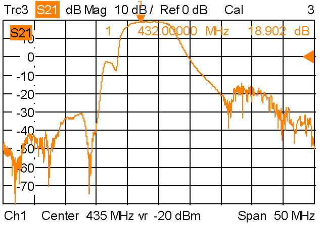
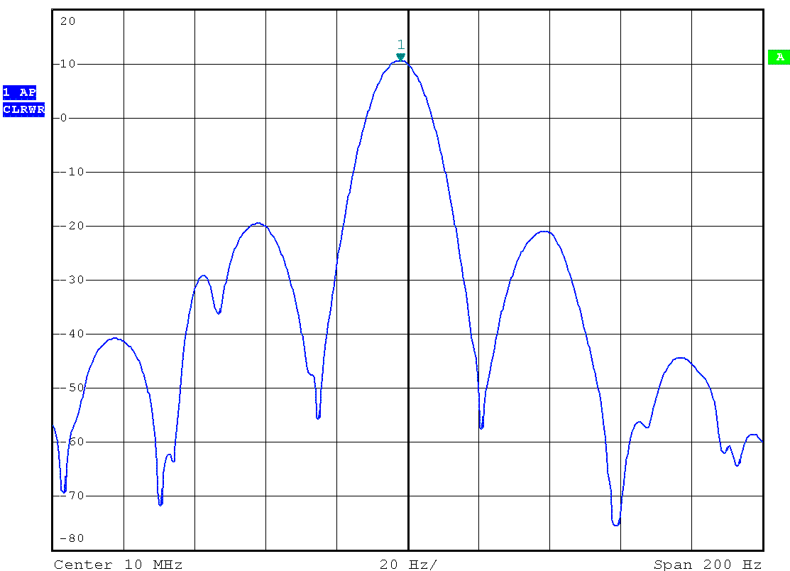
LNA 70cm


As written above the 70cm SAW starts to attenuate a lot around 437MHz. There was a type with broader response but it is available nowhere.
The overall gain is about 18..19dB which is in line with MMIC and filter datasheet.
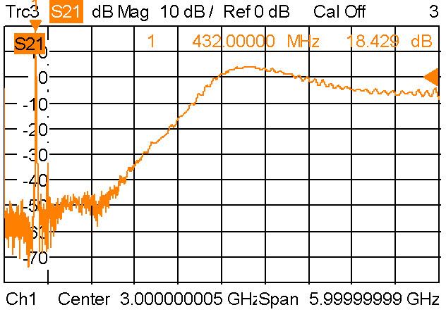
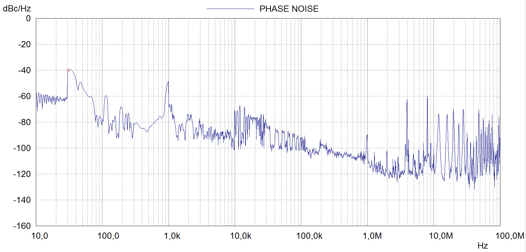
LNA 70cm wideband


Looking to the wideband response of the filter reveals that it looses its filter capabilities over 1200MHz.
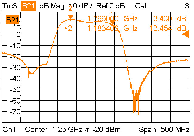
LNA 23cm


The filter used for 23cm is a bit wide. It exceeds the amateur allocation a lot at the lower end. At the upper end 1296MHz is already at the edge. The maximum gain is around 1180MHz with 13dB. For 1296MHz it results in roughtly 8dB gain only.
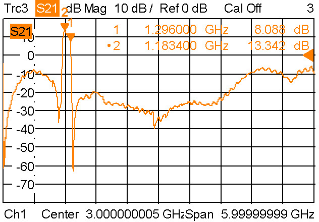
LNA 23cm wideband


The filter capability is maintained over a broader range and de-rates at over 5GHz.
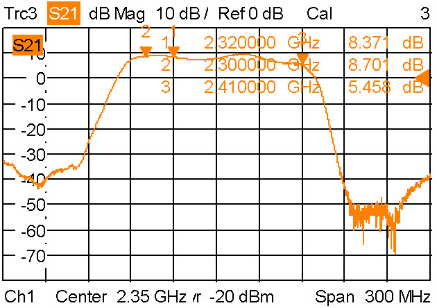
LNA 13cm


The filter for 13cm fits pretty well. Although the MMIC has even less gain the filter also has less attenuation than the 23cm type on 1296MHz. Therefore it also results in about 8db gain.
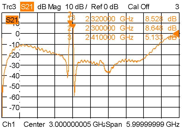
LNA 13cm wideband

4m 2020/June/01

After missing the big 2m ES last friday i had some luck on 4m today. Among others i worked GM4VVX, EA6FB, OH1KH, PA3FMP, GW8ASA, GU6EFB, EI8IQ and OY1OF.

reception reports on pskreporter.info for 4m on June 1st 2020 for DH5YM. map by openstreetmap contributors.

New 23cm transverter and DUR contest

Last weekend i tried to put my new 23cm transverter with 28MHz IF and the 100W PE1RKI PA together. The picture shows my ugly “transverter in a box” construction.

23cm transverter ugly test construction

I used this setup in the March 23cm DUR contest. My ODX was HA5YA via aircraft scatter about 550km distance. I also worked DL3IAE and OM5CM, both >400km.

OM Raachermaa

This is an traditional figure from the Erzgebirge. OM seems to do VHF contesting which is also popular there ;) But maybe not only the OM is smoking but the transceiver as Wellness eventually. Merry Christmas to all of you!

OM Raachermaa

Searching for some FreeDV QSO partner on VHF

Since i use Quisk for my HiQSDR i found it interesting to experiment with FreeDV again. Quisk can directly support using the FreeDV API and work in this digital mode without building lots of cables. Since i wanted to try the latest mode 700C i had to compile the library from the scratch and add the mode to the configuration of quisk. Below you can find recordings of my CQ call in the modes 1600 and 700C which were made loopback.
Now i search for a QSO partner preferably on 2m somewhere in the area around JO61. I can work relatively well direction southeast. So east OK might be good.

Mode 1600

Mode 700C

Please remember the 700C mode uses only 1kHz of bandwidth.
If you are interested in some tests just send me a email to dh5ym@darc.de

GPS 10MHz reference

Since some time i own a DF9NP GPSDO. Currently i only use it to lock my signal generator but i also want to use it for my microwave transverter OCXOs. When connecting a SMIQ signal generator and checking the signal output at 6GHz i noticed some +-50Hz jitter under the poor reception conditions at thelocation of this signal generator. So i want to look a bit closer into that topic. In China i ordered a Neo-M8N module that can be configured to provide a 10MHz clock at its timepulse output. I tried to compare it with the GPSDO and the OCXO of my SMY-02 signal generator.
Of cause the digital clock has significant jitter because it is generated by a CPU (specified with +-10ns).

Neo-M8N clock output at 10MHz

The picture of the timepulse at 10MHz shows, that it seems that comparing the clock to a stable oscillator over a relatively short period could be sufficient for adjusting the frequency of this oscillator to the GPS.

GPSDO, M8N, OCXO

The screenshot shows the oscilloscope triggered to the GPSDO (green). The output of the M8N module (yellow) shows the jitter and the adjustment range within 60 seconds (yellow shadow). The third (blue) trace comes from my SMY-02 which was locked to the GPSDO. The SMY signal shows some slight jitter compared to the reference. To me it is not clear if the cause is the reference or the locking in the generator. The clock from the M8N module shows significant adjustment of the clock frequency within the 60 seconds shown compared to the GPSDO which has a TCXO that is slowly compensated by the GPS inside the reference.
Looking to the signal in frequency domain shows this picture:

Neo M8N spectrum

There are rather close sidebands that require narrow band adjustment of a oscillator eventually locked to this GPS clock. Wideband the spectrum is noisy as well.

M8N phasenoise at 10MHz

Finally i took a short video showing the the scope triggered to the 10MHz OCXO reference of the SMY and comparing the GPSDO and the M8N output. The OCXO is slightly off 10MHz and therefore the picture is moving all the time. You can also see that the M8N is slowly adjusting compared to the GPSDO output.

GPS 10MHz GPSDO vs Neo-M8N and 10MHz OCXO