Sequencer with Attiny assembled

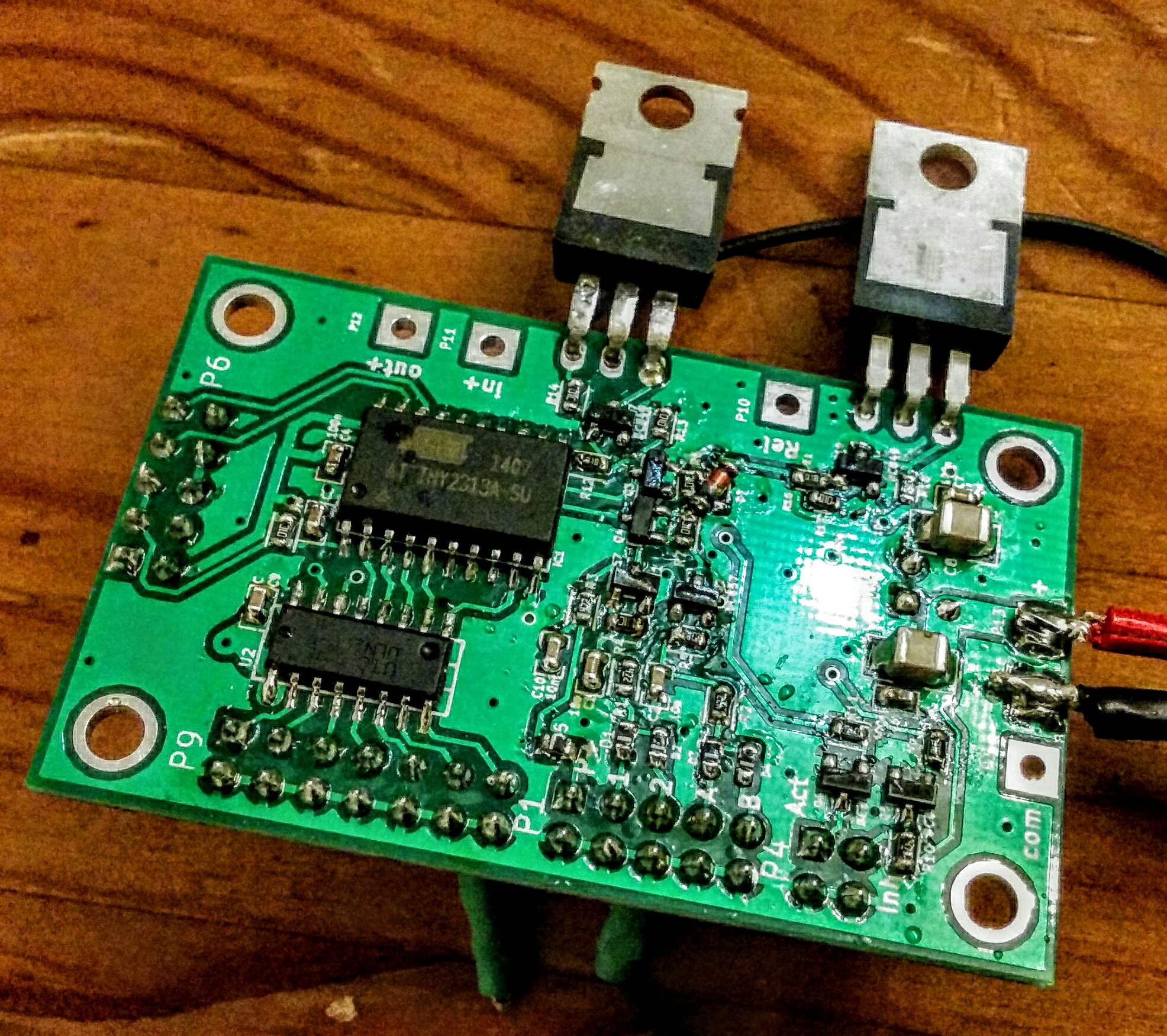
Attiny2313 + Uln2003 + highside FET switch for PA + lowside FET switch for RX-TX relais and a few bipolar Low Power stages on a two-layer board. The PTT input can be either high-side or low-side active. It also has lock input to connect several transverter to one antenna system. Via the driver IC a pulse relais and a fan can be controlled. There is also a Tx inhibit output that can be used with Yaesu tranceivers.

Schematic:
Attiny Sequencer Rev2 schematic
The circuit has two PTT inputs and two Error inputs (decoupled by diodes). A active high PTT input is available as well. There is a highside FET switch that can be used to drive a PA and a lowside FET switch that can be used for an RX/TX relais. The TX inhibit signal is available to drive the inhibit input of Yaesu transceivers. The active out is used to signal a sequencer in TX mode. This can be used to lock other sequencers via the error input. The ULN2003 driver is currently configured for another RX/TX relais, a fan which is running until 30s after releasing the PTT, another low active signal parallel to TX-inhibit (as PTT for TRX without TX inhibit) and output signals for a pulse relais (bi-stable RF relais). The serial interface (also used for ISP) is unused in the application. It might be possible to connect a temperature sensor for example.
The missing connection from Q4 to R7 is a print error.

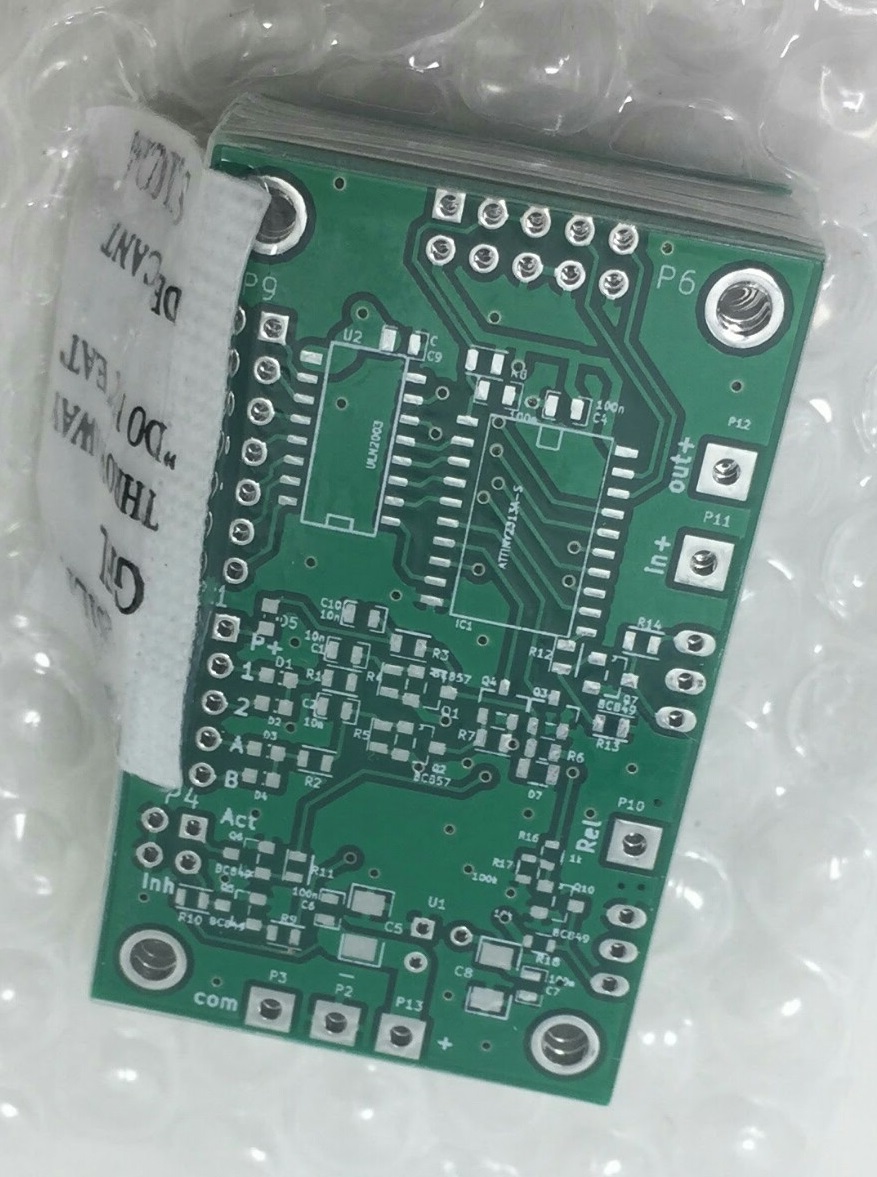
The design was done with KiCad which is a open source PCB layout system. The code for the microcontroller was written in C. The 2k program memory are almost full now but one might be able to optimize. If you are interested in the design data let me know. I also have some spare PCB left over.

I wonder what else could be implemented with this PCB with the small program memory size. Feel free to give some ideas.

RX/TX sequencer new PCB from China

2nd version of the PCB i designed over 2 years ago. Hopefully without bad errors i hope ;) Lets see when the shipment will arrive…
I corrected the package of the microcontroller and swapped a few signal pins in order to gain some flexibility with the software.

Sequencer version 2 PCB

Attiny RX/TX sequencer

RX/TX Sequencer with Attiny

Sequencer for Transceiver and Transverter sequence control made around a Attiny2313. It can switch a RX/TX relais lowside, a PA supply highside, has “active” and a “TX inhibit” outputs. Furthermore there is a input to lock the PTT from a second sequencer (switch on the RX/TX relais only). There is an extra 7bit output driver that is in that example used to drive a pulse controlled RF relais.

U02 DDS, by DJ0ABR

For some tests with WSPR i purchased a DDS PCB from Kurt DJ0ABR. The PCB comes with most parts assembled and you just need to solder  some easy stuff as well as mount it into an enclosure. There is a microcontroller  that interfaces with a PC or  operates the DDS alone. It can be used as synthesizer  for AM FM, as  a wobbler unit as  well as beacon for WSPR, CW and DSTAR. Frequency range is from medium wave to 160MHz.

image

Edit:

Today i added the GPS receiver and connected the DDS to a Outbacker 1899 antenna placed on the heating inside the room. During the sunset some stations received my 50mW signal on 20m.

wsprnet_20m_50mW

wsprnet_20m_50mW

[The list is a screenshot from WSPRNET.org]


once again – DL1DBR rotator control

My rotator control unit (design by DL1DBR) is more or less finished now.
All the stuff is in the enclosure and working. Items that i needed to solve were:
– deal with some bug in the PCB print were the names for the connectors for Keys and LCD are mixed up ;)
– connecting the KR600 rotator which is 24V AC with end switches which needs two driver PCB in parallel to keep this function
– change the connection of the poti in the rotator unit to measurement voltage over the complete 500 Ohms
– change the software to allow for stopping the motor in the moment the direction key is released (before it stopped only on pressing the OK button)
– changing some libraries to get it compiling in my environment
– deal with the CDC UART (i replaced the CDC done with Attiny2313 by a FTDI UART-USB converter, this works in all environments in contrast to the CDC)
– search for a suitable 24V AC power supply for the motor
– get the DC for the controller working in the environment with the motor (i decided to spend a 2nd trafo for the logic because that was the fastest way to get rid of the interference which disturbed all the resistor measurements)

Rotor Control unit DL1DBR

Rotor Control unit DL1DBR


The following picture shows the inner of the rotator control unit.
Inner of Rotator control unit

Inner of Rotator control unit


Starting with the right upper edge: Thats the 24V AC transformer that supplies the motor of the rotor unit. Below that there is a small black part. Thats the 15V transformer that generates the voltage for the digital part. Using the 24V from the motor supply resulted in crazy measurements due to the strong interference from the motor. At the lower edge you can see the display PCB mounted to the frontside of the enclosure together with the keys. Above there the brown PCB is the main control unit that is driven by a Atmega controller. It gets its supply from the blue PCB on the left edge of the enclosure which is a DC/DC converter that generates about 8.5V out of the voltage from the black transformer. The PCB above the controller PCB is the driver for the motor. Actually its two identical PCBs stacked. The capacitor for the phaseshift of the motor resides in between this stack. The PCBs use each two solid state relais for switching the supply voltage.
For the remote control of the unit i replaced the Attiny CDC implementation by a FTDI USB-UART adapter that is mounted at the left side. Its the silver part there.
In case you have questions… Let me know.

Rotator control unit DL1DBR about 90%

image

Since quite some while i try to get the DL1DBR rotator control unit completed. I changed the controller firmware a bit, adopted the driver connection for my KR-600 and started to build the stuff into an enclosure. Now only a few wires have to be connected and some holes need to be drilled.
The control unit can drive up to two rotators and its possible to control it via a USB connection out of the most logging software.
It also has some preset tables for directions that are often used.

Veröffentlicht mit WordPress für Android

HDLC/AX25 to serial KISS converter

Last day´s i continued working on my HDLC/AX25  KISS TNC software. It is far away from beeing finished but may be useful for someone already.

What´s it ?: You can connect an RF modem with NRZ or NRZI coded output. I just tested 1k2 and 9k6 bps AX25 modems. The microcontroller (currently Atmega644) decodes the frames and forwards it to a host PC via a serial KISS interface. This interface supports plain KISS, SMACK and RMNC-CRC-KISS. What´s not in this version is the CRC check for the received packets. This will be one of the next steps.

What it should be somewhen: A complete KISS/SMACK TNC which uses an external modem. Most probably this will not work on a Atmega644 because of the RAM limitations. I try to get it into an Atmega8515 with external SRAM.  Another option might be a Atmega1281 or 1284 without external memory. For 1k2 (not sure for 9k6) is would also be possible to add the modem functionality directly to the microcontroller and therefore to safe the external modem.

AVR HDLC decoder source

Whispers at shortwave…

Usually shortwave is not my favourite area of amateur radio. But inspired by an article from Eike-DM3ML i did some experiments
with WSPR (weak signal propagation reporting). It is a automatic beaconing network invented by K1JD. It is really exciting to see
low power stations appear at the display even with a really small receiver antenna. In addition i wrote some software for my
Atmel microcontroller that controlls a small DDS signal generator circuit. With this simple setup it is possible to transmit WSPR beacons
at 5dBm output power. Unfortunately 5dBm are not enougth to be heard by anyone with my small indoor antenna. Maybe i should
build an amplifier ;)

WSPR at 80m in JO61

WSPR at 80m in JO61