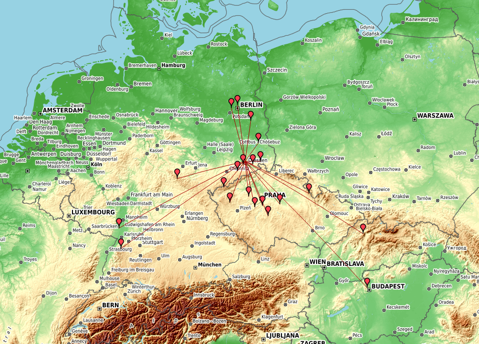
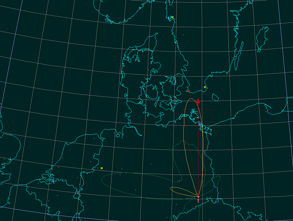
Recently my new 23cm LNA showed up here. For the DUR activity contest today i integrated it into my transverter system. 9cm got double points this month. Therefore i also tried to be active there. Not that much activity and only 2 QSO. The 23cm result was quite good due to some nice DX with SM6VTZ, HA5UA, HA5YA and OM5CM.
23cm result October DUR // Image created by DL4MFM log analyzer. Kartendaten: OpenStreetMap-Mitwirkende, SRTM | Kartendarstellung: OpenTopoMap (CC-BY-SA)
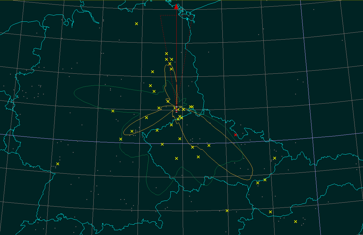
Originally planned some more QSO but in the end there where more time constraints than expected. Therefore only 21 QSO on 23cm sunday morning. I skipped all other bands. 70cm was not ready anyway. ODX HA5KDQ with >500km.
Image created by DL4MFM log analyzer. Kartendaten: OpenStreetMap-Mitwirkende, SRTM | Kartendarstellung: OpenTopoMap (CC-BY-SA)
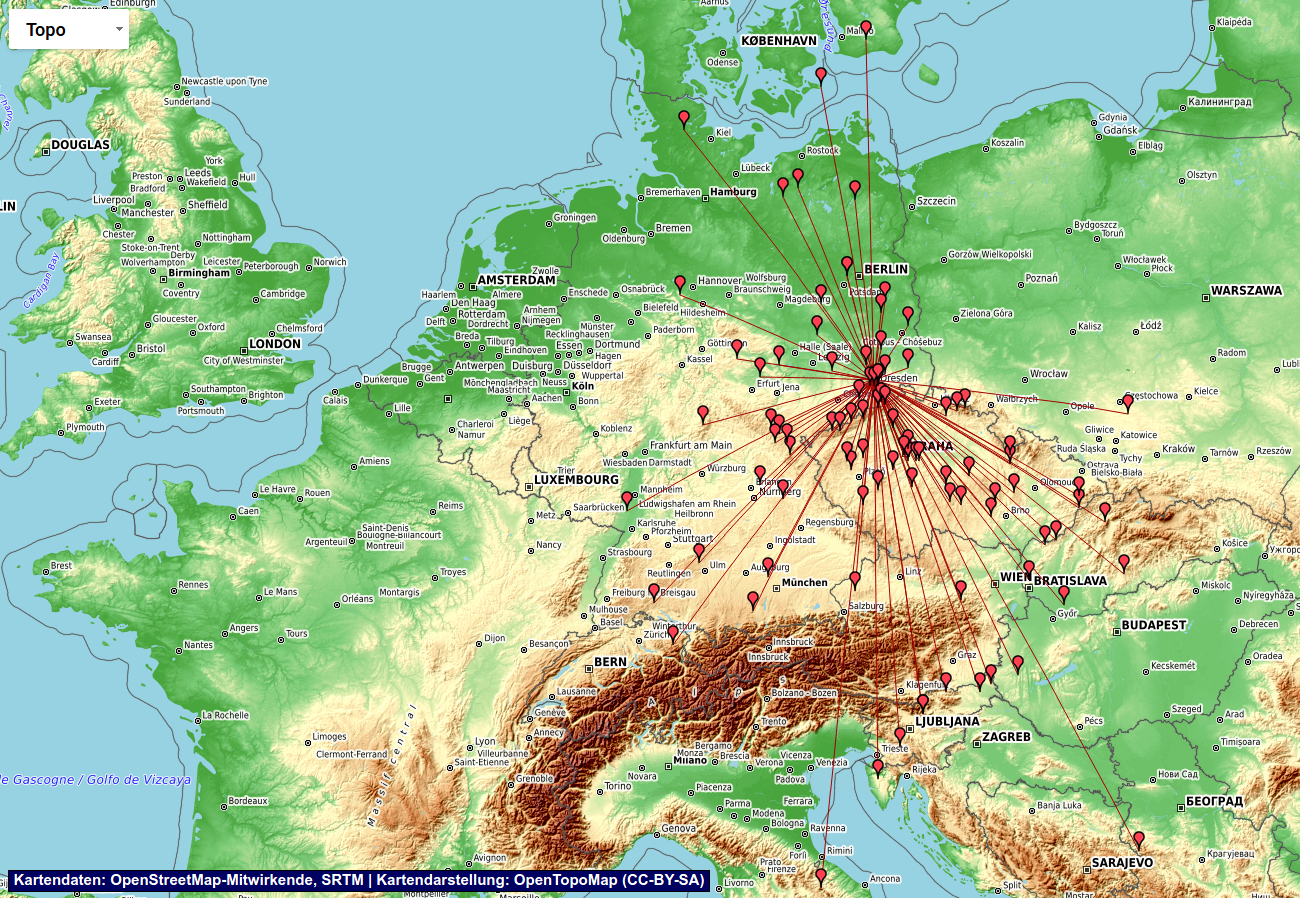
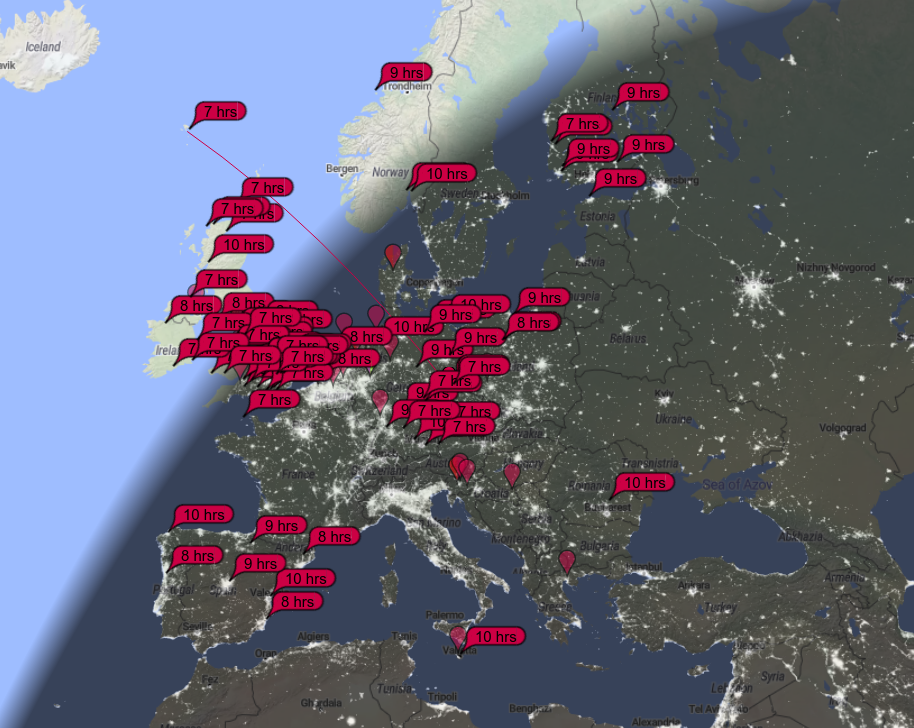
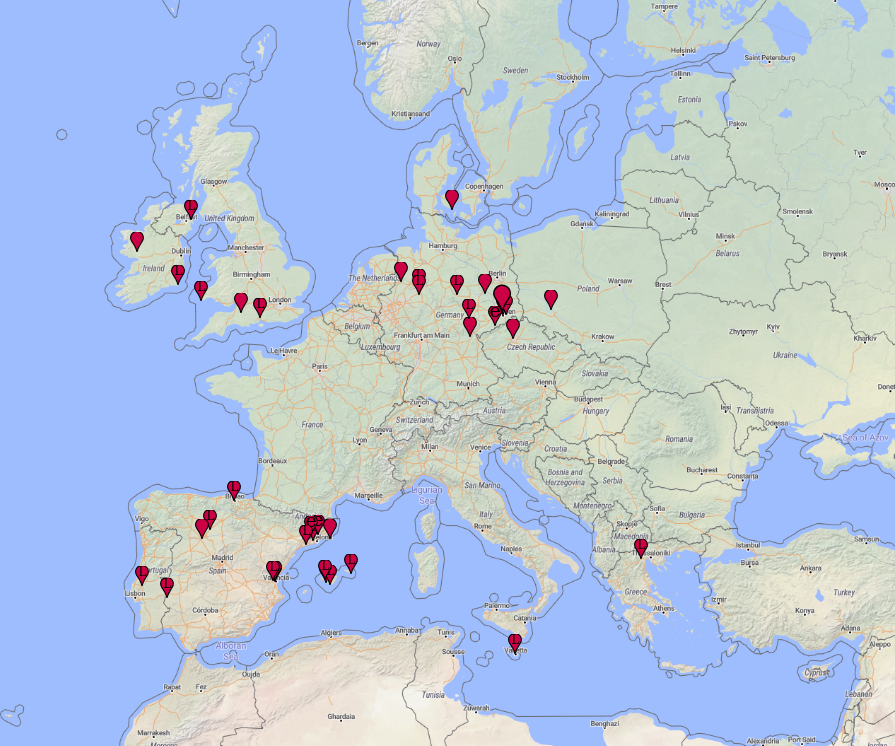
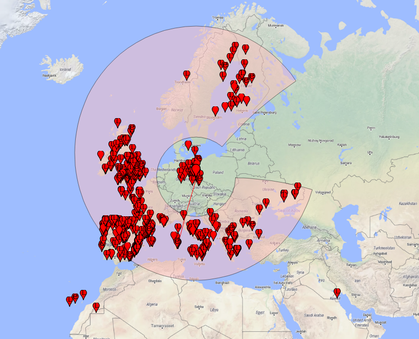
I planned to make some QSO from home. In the end i had about 10h of participation mainly during the night and sunday morning. The setup was 4ele and 200W with my HiQSDR and ME2HT transverter. The raw result shows 95QSO with highlights YT4B in CW random and IQ5NN even in SSB via aircraft scatter. 7S7V and 5P5T had pretty strong signals here.
Log results DH5YM September 2020 – visualized with DL4MFM log analyzer – (C) openstreetmap contributors
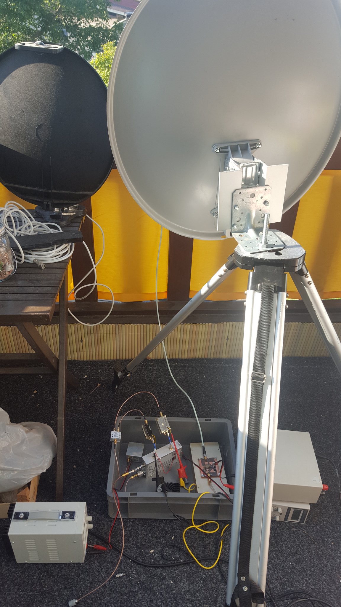
This weekend i did some new trials with QO-100. In the picture you can see parts of setup i used. This time the TX setup was purely classic. You can see it in the grey box in the foto below. FT-817 on 2m as IF followed by an upconverter made from some old UMTS measurement equipment block (silver box in the middle). It does dual upconversion with high-side LO. The LO consist of an ADF4351 each (the two smaller boards above the converter). The reference is a 96MHz OCXO of G8ACE design (left of the PLL boards). The converter block generates up to 200mW on 2.4GHz. I drive a WLAN PA (black box) that probably generates 1W. And the final PA is a MRF21030 PA (on the big heat sink on the right). It provides about 10W in SSB. The antenna is my 60cm offset dish with the DJ7GP patch (the one that has the round patch element). Left to the grey TX dish you can see a black 40cm camping dish with Octagon LNB and TCXO modification. But instead i used the BATC websdr this time. The reason is the amount of cable i currently have. I use 3 power supplies (28V, 13.8V, 5V). Reducing the number of required cables is one of the next steps. However i was pleased to do some nice QSO.
Since quite some while there are 5.7GHz PAs intended for video transmission from drones to ground. Those PA are made with 5GHz WLAN IC and very cheap (below 30Euro including shippment). These PA can be used for 6cm amateur radion but need some modification upfront to generate a usable amplifier.
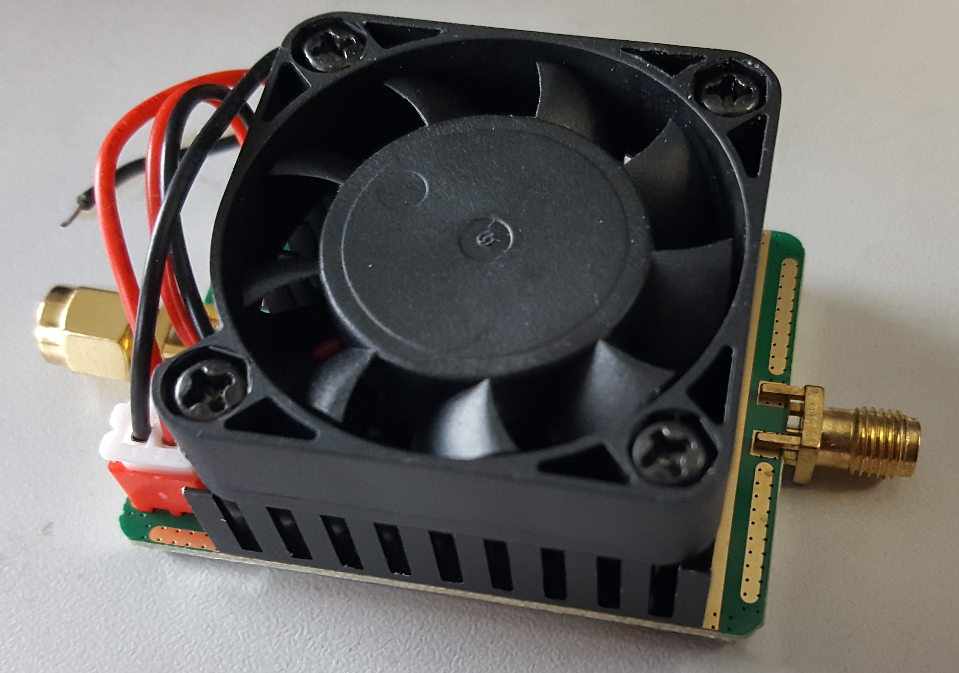
PA6cm 2.5W top side view
The PA comes with heatsink, small fan and a short power cable.
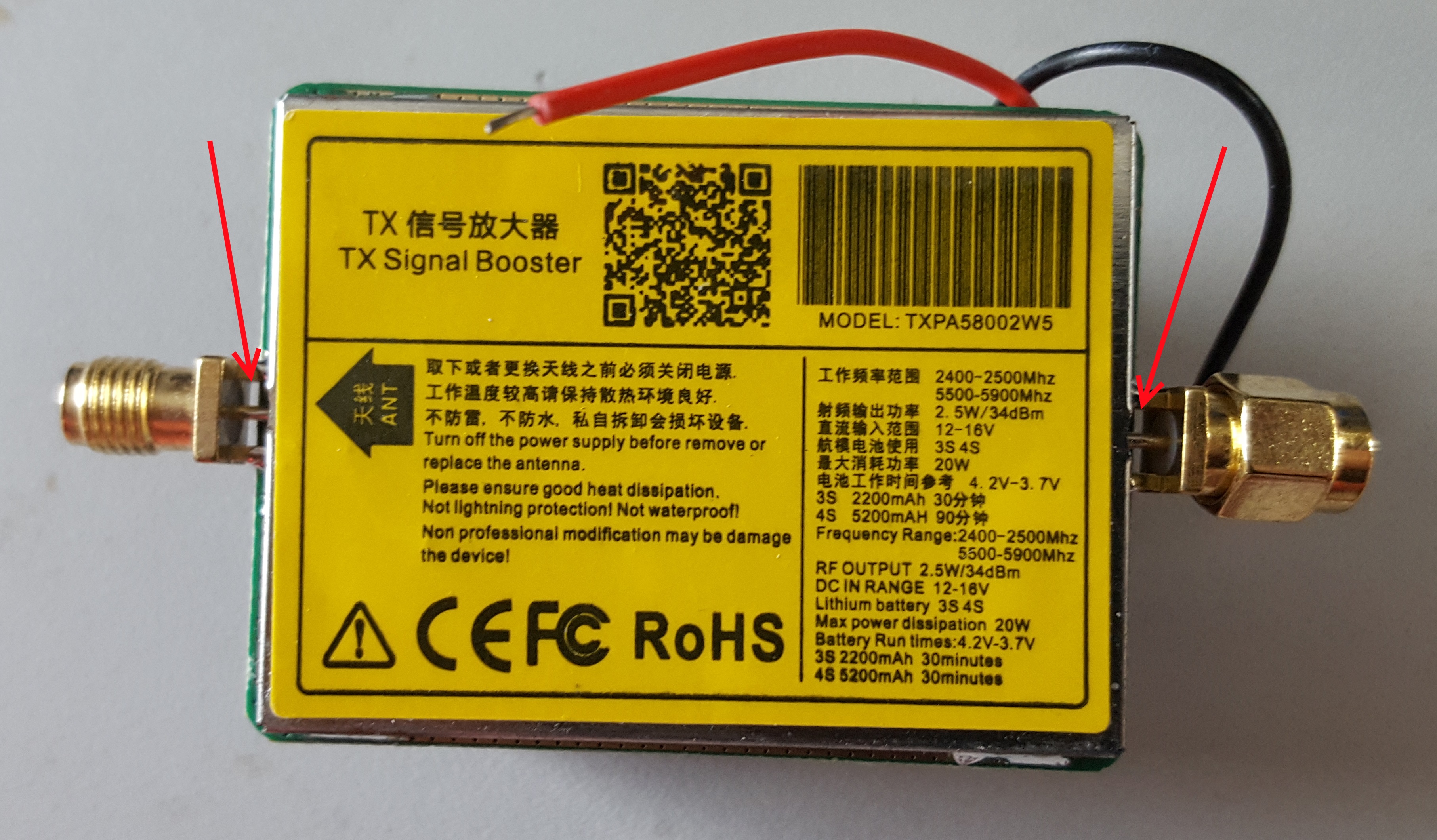
PA6cm 2.5W bottom side view and technical info
The PCB side has a metal cover that has a sticker with some technical data. The PA is supplied with 12-16V. It is intended for 5.7GHz operation. The sticker also mentions 2.4GHz but the PA will not work there. The specified output power is 2.5..3W although the vendors usually state 5W. You will not reach 5W.
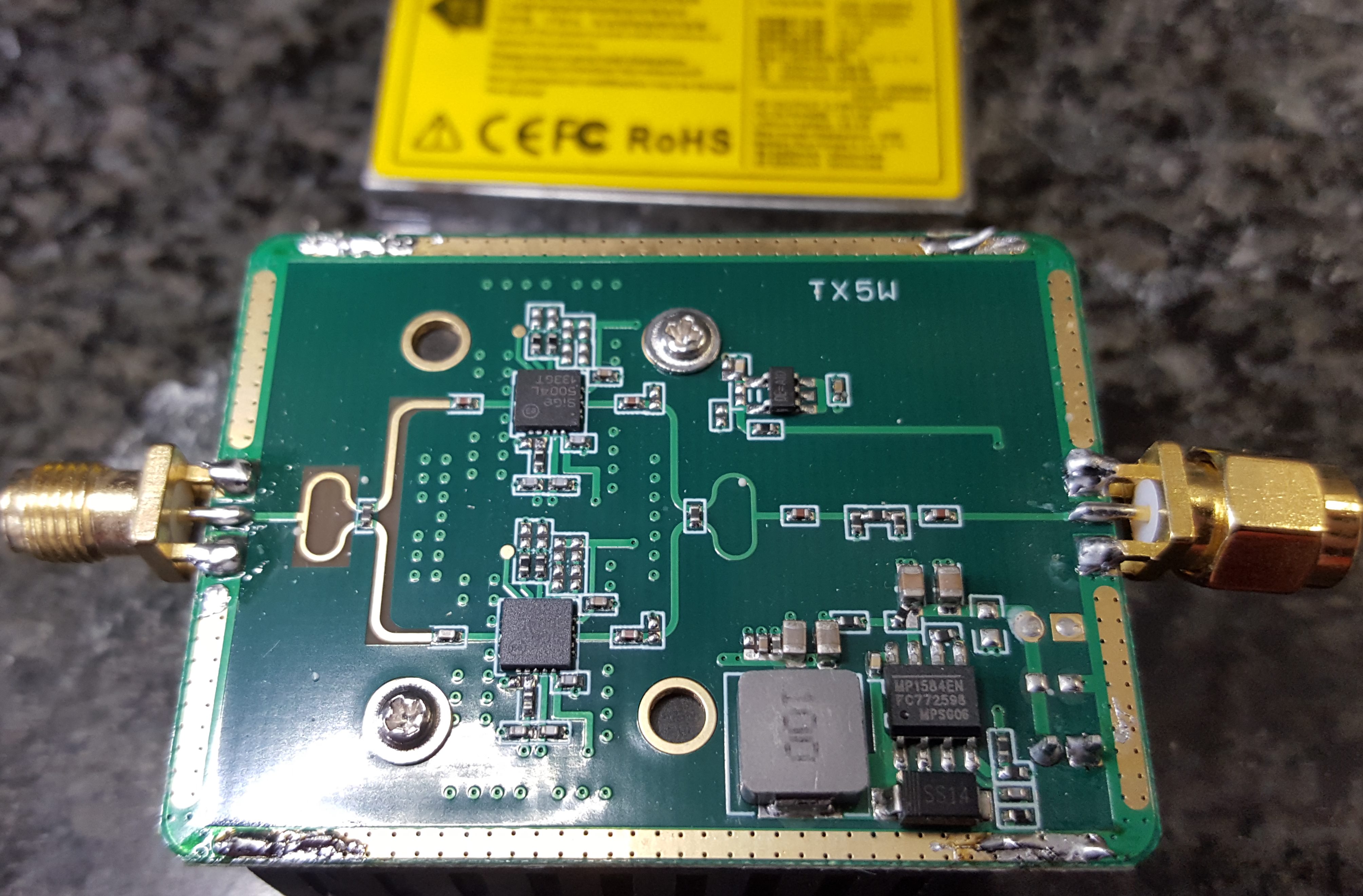
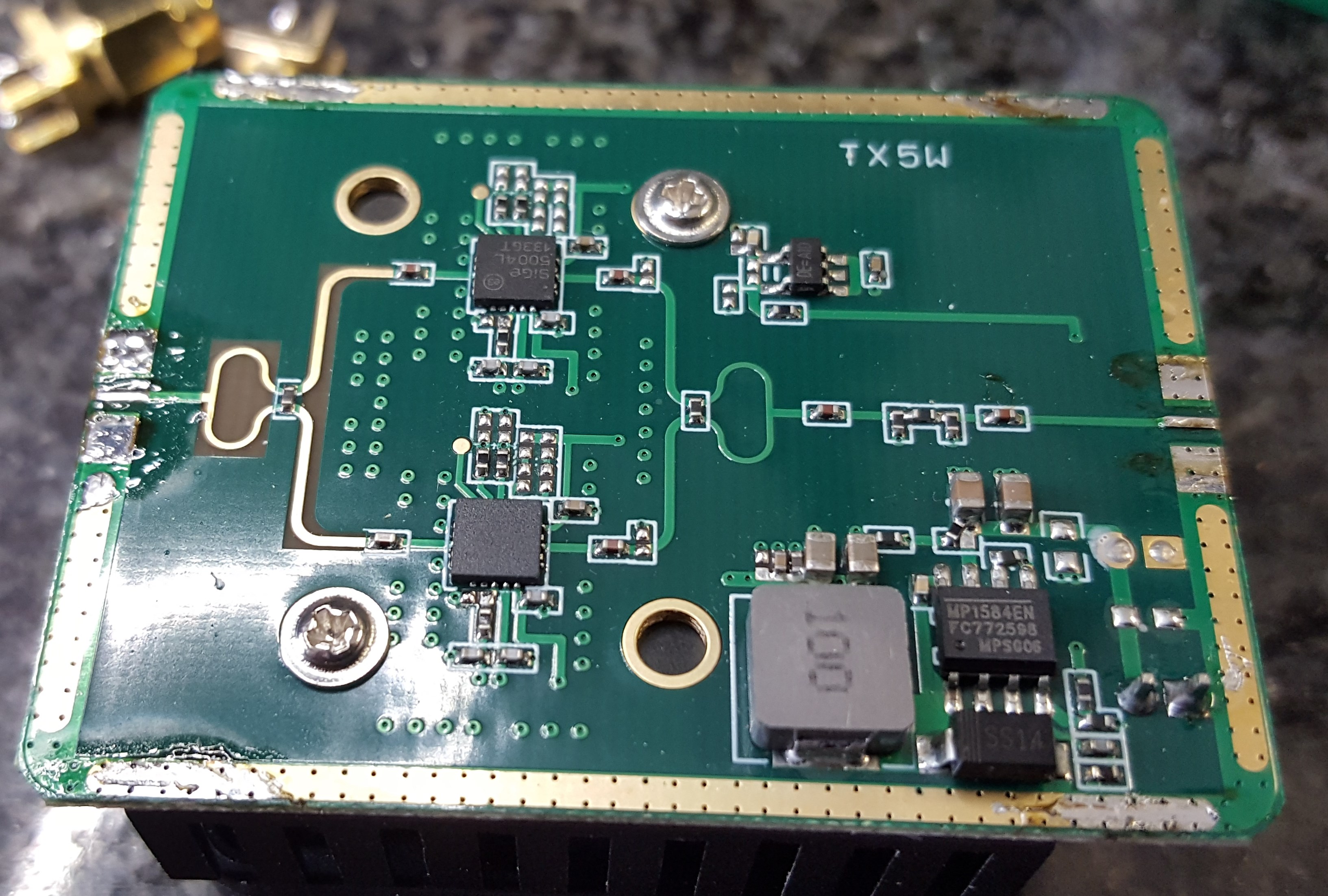
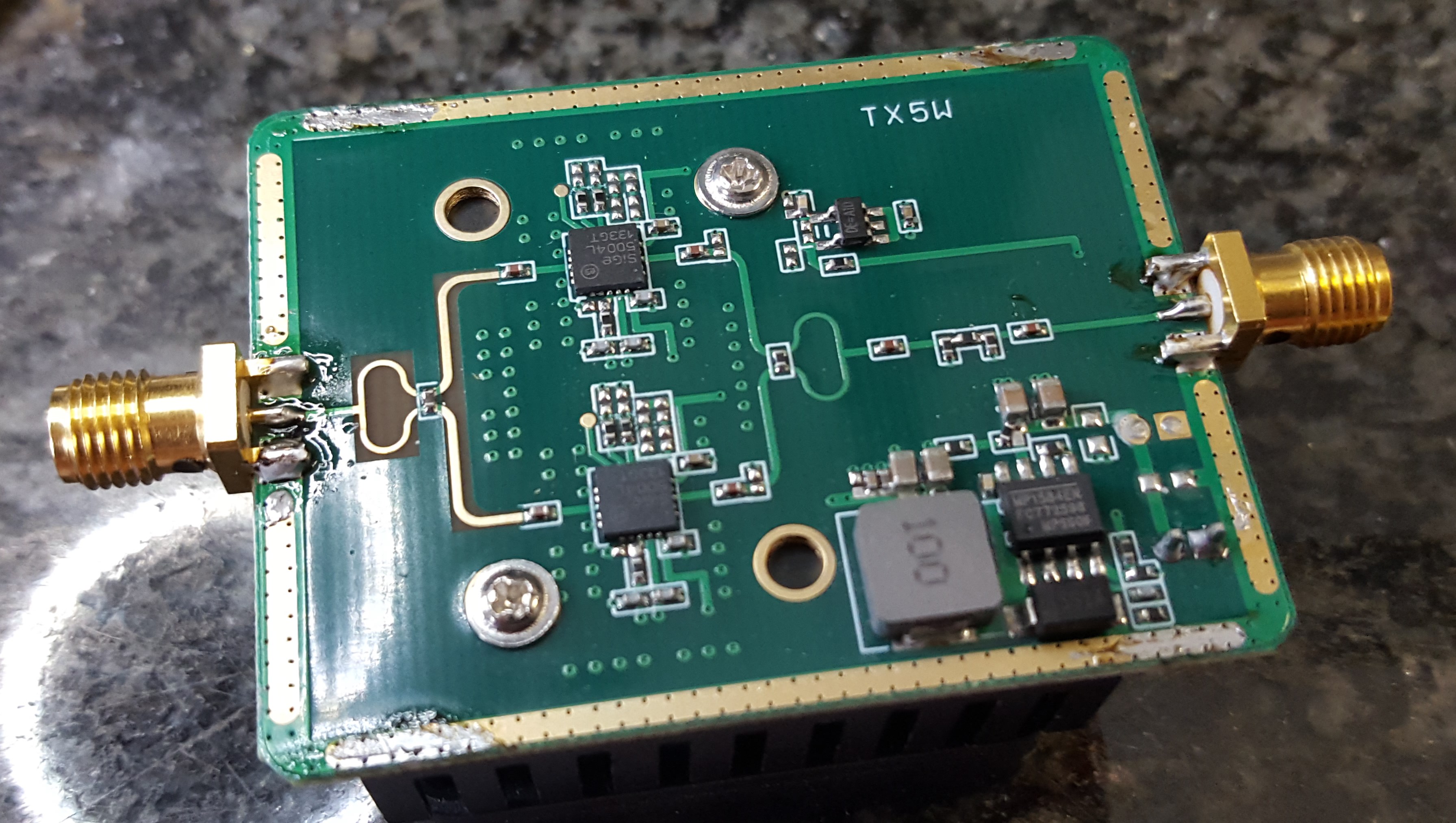
PA6cm 2.5W with metal cap removed
Removing the metal cover shows that the PA PCB contains two Sige 5004L WLAN amplifier IC, some splitter/combiner, an input attenuator and a power supply circuit. The connectors are Reverse SMA (RSMA) and they are mounted really poor. I would not even try to use the PA with those connectors and the air gaps to the PCB.
PA6cm 2.5W RSMA connectors removed
Now the silly RSMA connectors are removed. The pads need to be cleaned. Also clean the ground ring to prepare re-assembly of the shield later on.
PA6cm 2.5W with new SMA jacks soldered
Solder some new SMA connectors. The grounds of the SMA connectors shall touch the top side of the PCB. You need to shorten the ground connectors a little bit. Likely you do not have connectors intended for the PCB thickness. You may solder the other side for mechanical reason. Solder the inner pin of the SMA last in order to prevent breaking the RF trace.
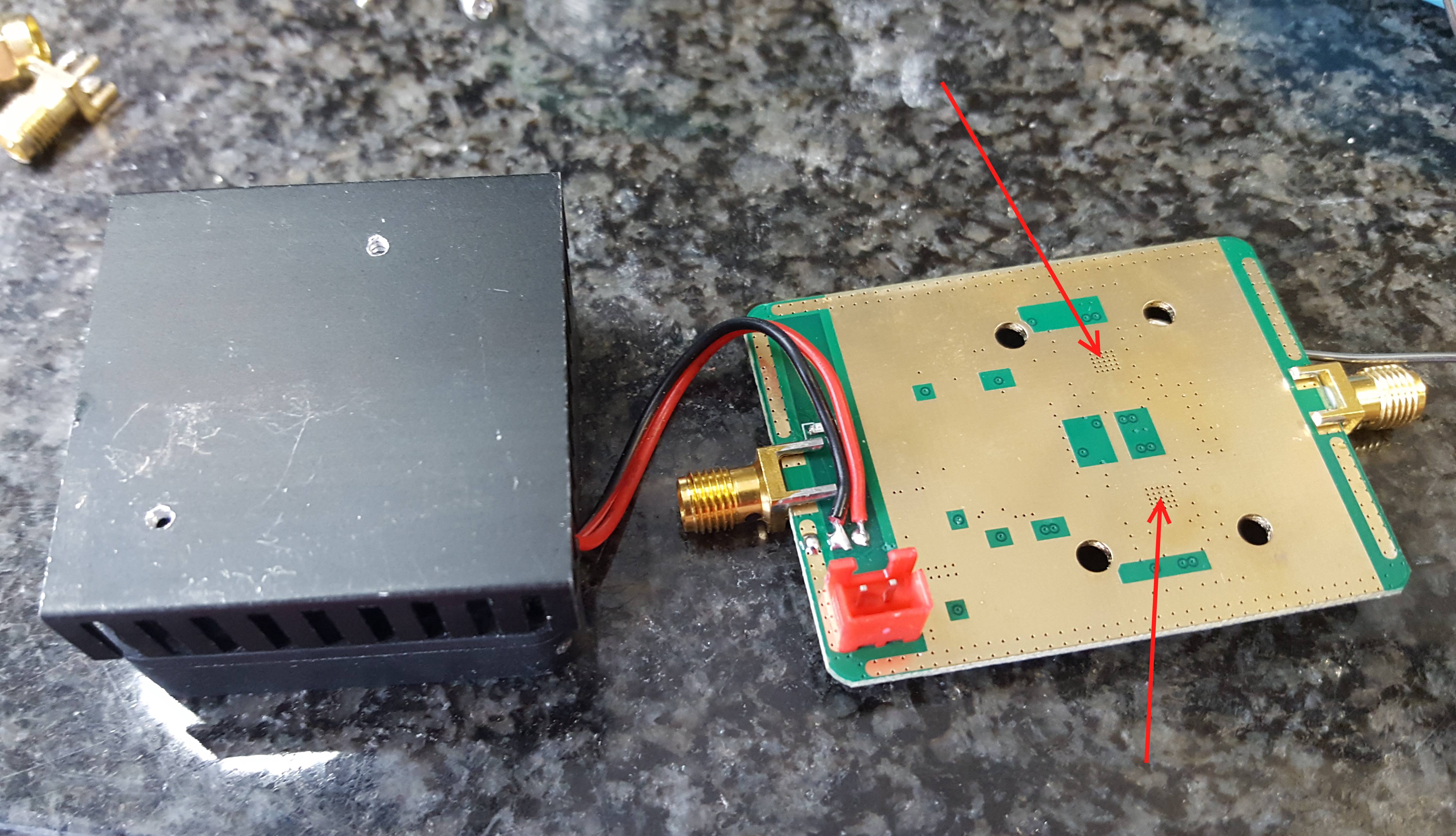
PA6cm 2.5W PCB removed from heat sink – no thermal paste
Some attention needs to be put on the thermal conductivity between PCB and heat sink. Removing the PCB from the heat sink shows that cost optimizations safed the thermal compount which makes the heat sink almost useless. So add some thermal paste to the marked areas below the amplifier IC. Probably the switcher IC needs some cooling as well.
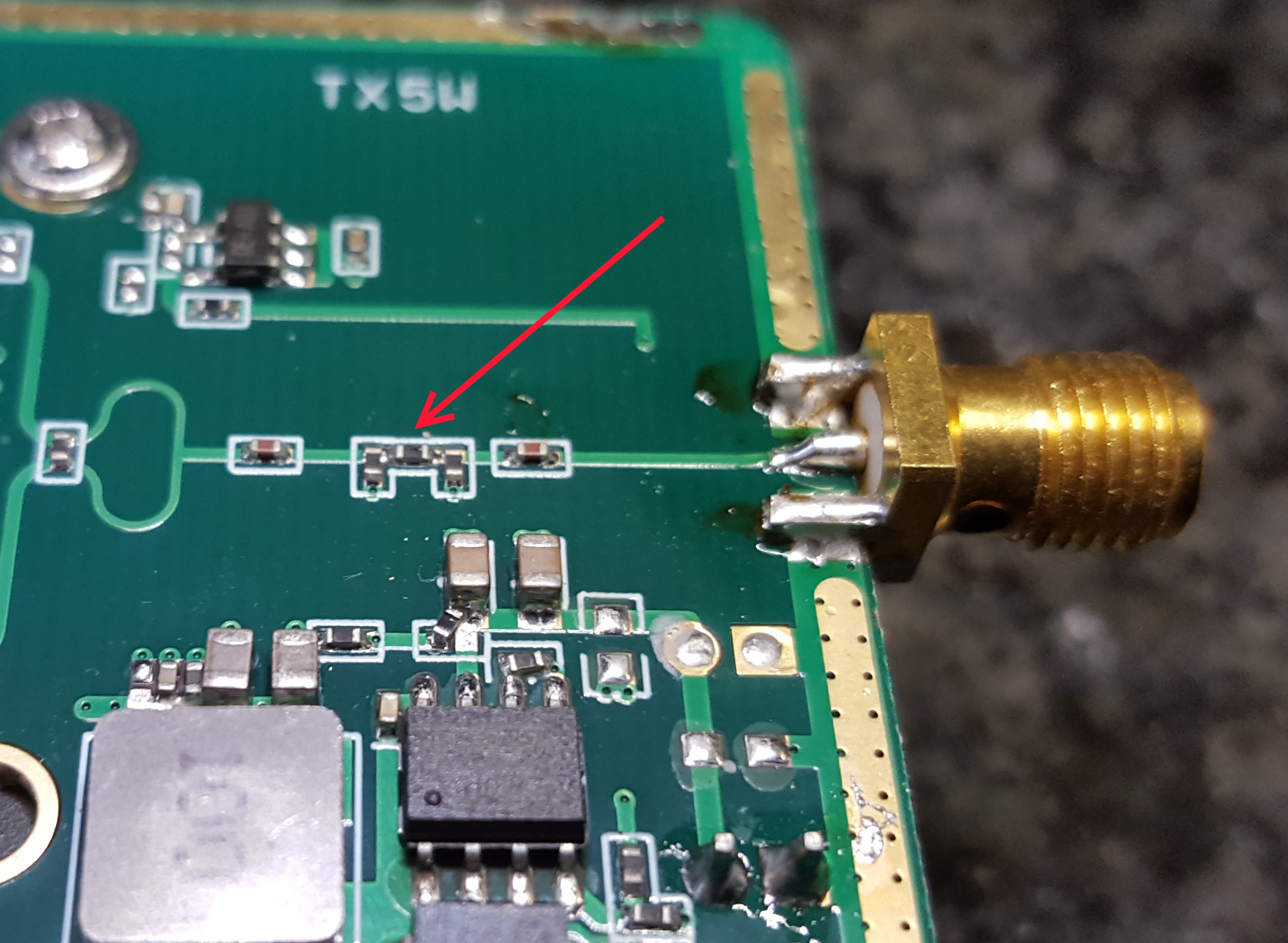
PA6cm 2.5W location of input attenuator
The PA PCB contains a input attenuator. The default attenuation is around 18 to 20dB. If you have less input power you might want to change it. For my measurements i removed the 3 resistors and soldered a 0-Ohm upside down to the middle resistor position. After everything is modified and tested you will likely want to re-assemble the metal shield.
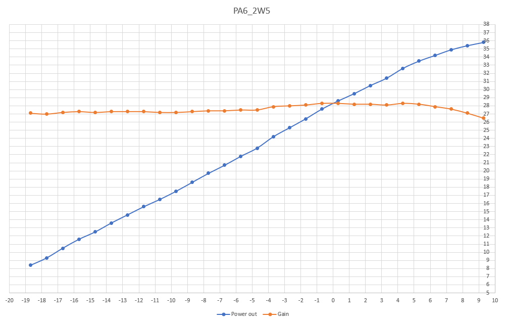
The PA has about 27-28dB gain and my sample achieves 3W output at 7dBm (5mW) input and a current of 1.3A at 12V. Saturation might be somewhere at 4W with 10mW of drive and 1.5A current.
Input/Output power [dBm] and gain [dB] after all modifications of the 6cm PA
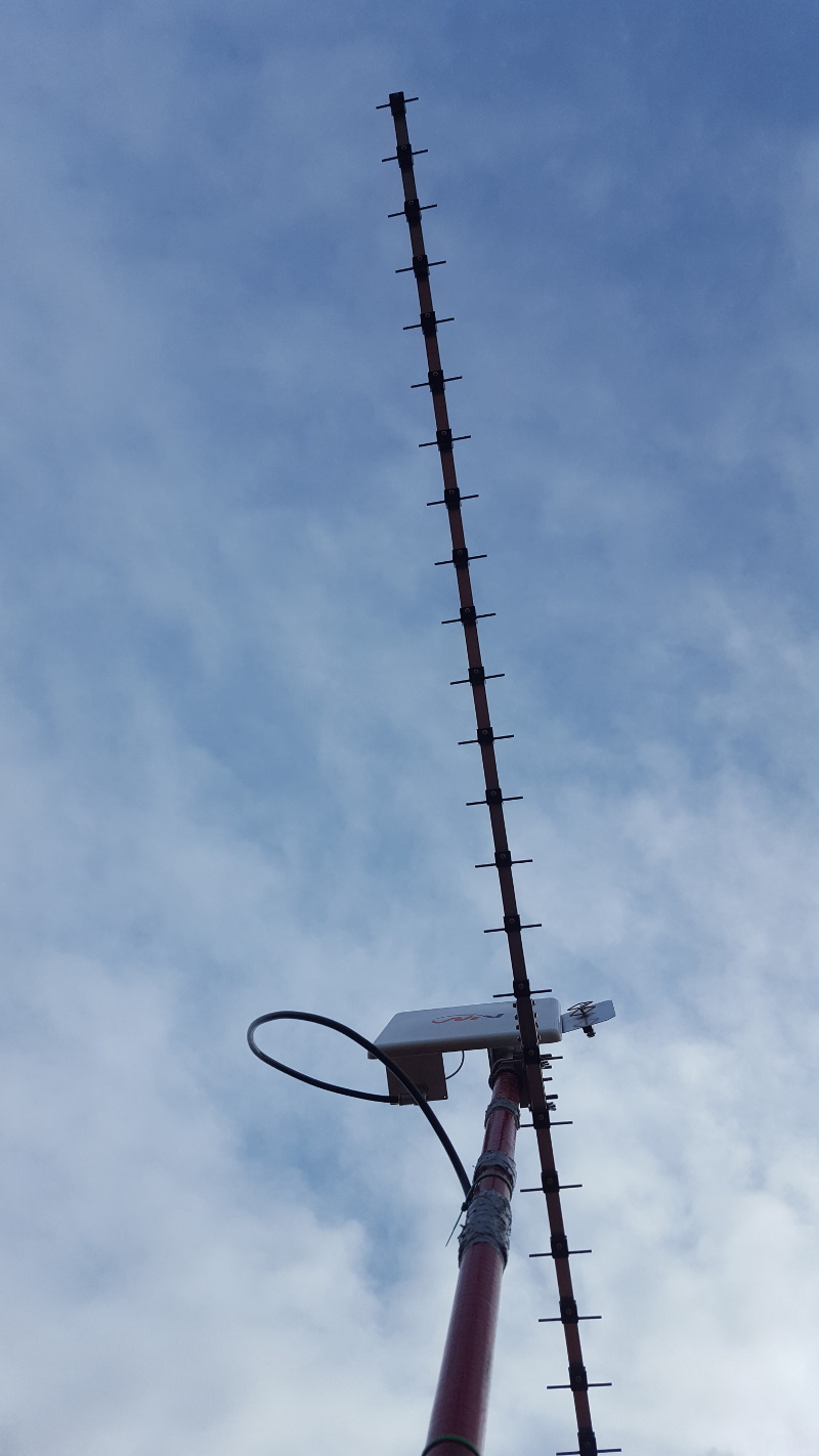
I was working the contest from home and part time. The 23cm transverter with 10m IF and the HiQSDR work pretty well. I used the Quados4 antenna since the 36ele ordered was still stuck in customs. ODX was HA5KDQ and in total 41QSO and 6900 points raw score. I also made some QSO on the higher bands on request. 3x 9cm, 1x 6 and 3cm each.
23cm map of reached contacts by dh5ym during microwave contest june 2020
After missing the big 2m ES last friday i had some luck on 4m today. Among others i worked GM4VVX, EA6FB, OH1KH, PA3FMP, GW8ASA, GU6EFB, EI8IQ and OY1OF.
reception reports on pskreporter.info for 4m on June 1st 2020 for DH5YM. map by openstreetmap contributors.
Today there was some good ES on the VHF bands. I managed to do some QSO. The FT8 monitor received quite an amount of stations. MUF moved >200MHz and there were some spots of stations from EA/CT… I did not receive anything on 2m.
4m FT8 traffic received by DH5YM FT8 monitor 2020/05/20. Map data by Openstreetmap contributors and waypoint data by pskreporter.info
worked stations: EA6XQ, EA3WD, EA5DF, EA6SX, OK1AGE, DL6AKK, CT1BXT, EA5TT
There was some SSB traffic as well. I did not have time to try. Some SSB stations call above .200 and cannot be answered anyway by DL stations.
6m FT8 traffic received by DH5YM FT8 monitor 2020/05/20. Map data by Openstreetmap contributors and waypoint data by pskreporter.info
Last weekend i tried to put my new 23cm transverter with 28MHz IF and the 100W PE1RKI PA together. The picture shows my ugly “transverter in a box” construction.
23cm transverter ugly test construction
I used this setup in the March 23cm DUR contest. My ODX was HA5YA via aircraft scatter about 550km distance. I also worked DL3IAE and OM5CM, both >400km.