
This time no operation from hill. Just a few QSO from home. HiQSDR + ME2HT-PRO + PA + DK7ZB Oblong. Few hours of operation saturday evening and sunday afternoon. 78 QSO and about 18000 points claim.
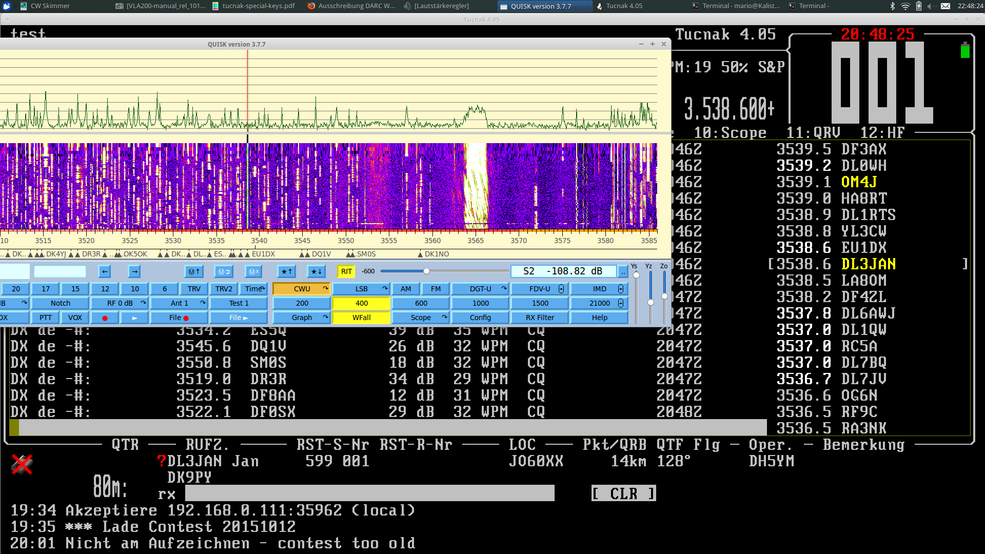
The screenshot shows the great Tucnak log.
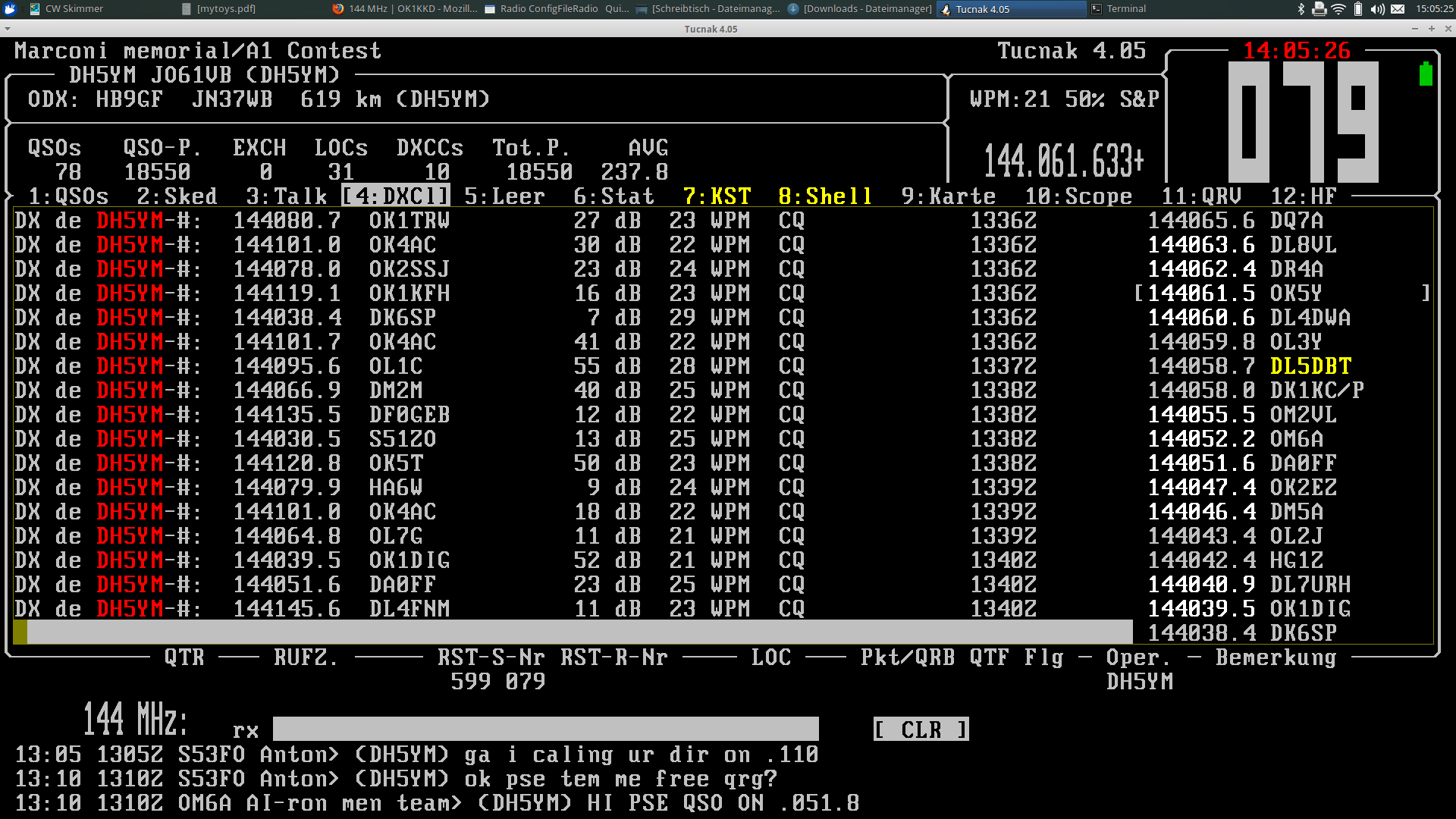
Some signals look very awful on the band…
I will not tell who it was ;) Hopefully the signal can be improved.
Category Archives: Amateur Radio
6cm Pipecap filter [part 2]
I shortened the probe pins of my experimental pipecap filter to 5mm in order to get rid of the unwanted response around 7GHz. As expected the filter is rather narrow now and the attenuation increases a lot.
Marcel made some new measurements up to 14GHz in order to see how the suppression behaves. It looks a lot better now but you can also see that at the upper end of the measurement range the attenuation is very low (keep in mind that the probes are nice quarter wavelength antennas there).
The following picture shows the filter tuned to the 6cm band:

pipecap 5mm probes 5760MHz
The passband attenuation is now always somewhere in the range of 2..3dB.
Tuned to the upper end of the possible range you see that it behaves more than a lowpass than a bandpass ;) The passband gets a bit wider.
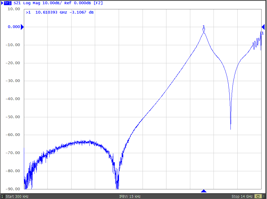
pipecap 5mm probes 10610MHz
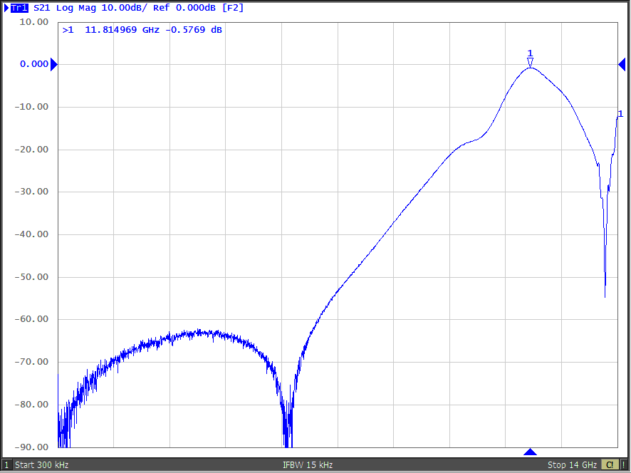
pipecap 5mm probes 11815MHz
I would assume that it makes most sense to design the probes beeing quarter lambda for the frequency were the notch of the filter appears (or slightly above). Since this depends on the frequency you want to tune the filter to you need to consider that before you make the filter.
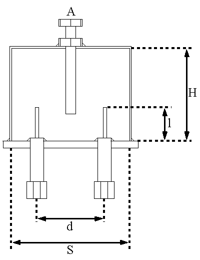
Pipecap filter dimensions
IC-E92 spectrum
Triggered by some forum discussion about interference risk of operating repeaters in neighbor channels in 6.125kHz channels I was curious about the TX spectrum of my IC-E92. The measurement was done radiated. I checked for neighbor channel interference. You can see the delta values bottom right.
FM wide:
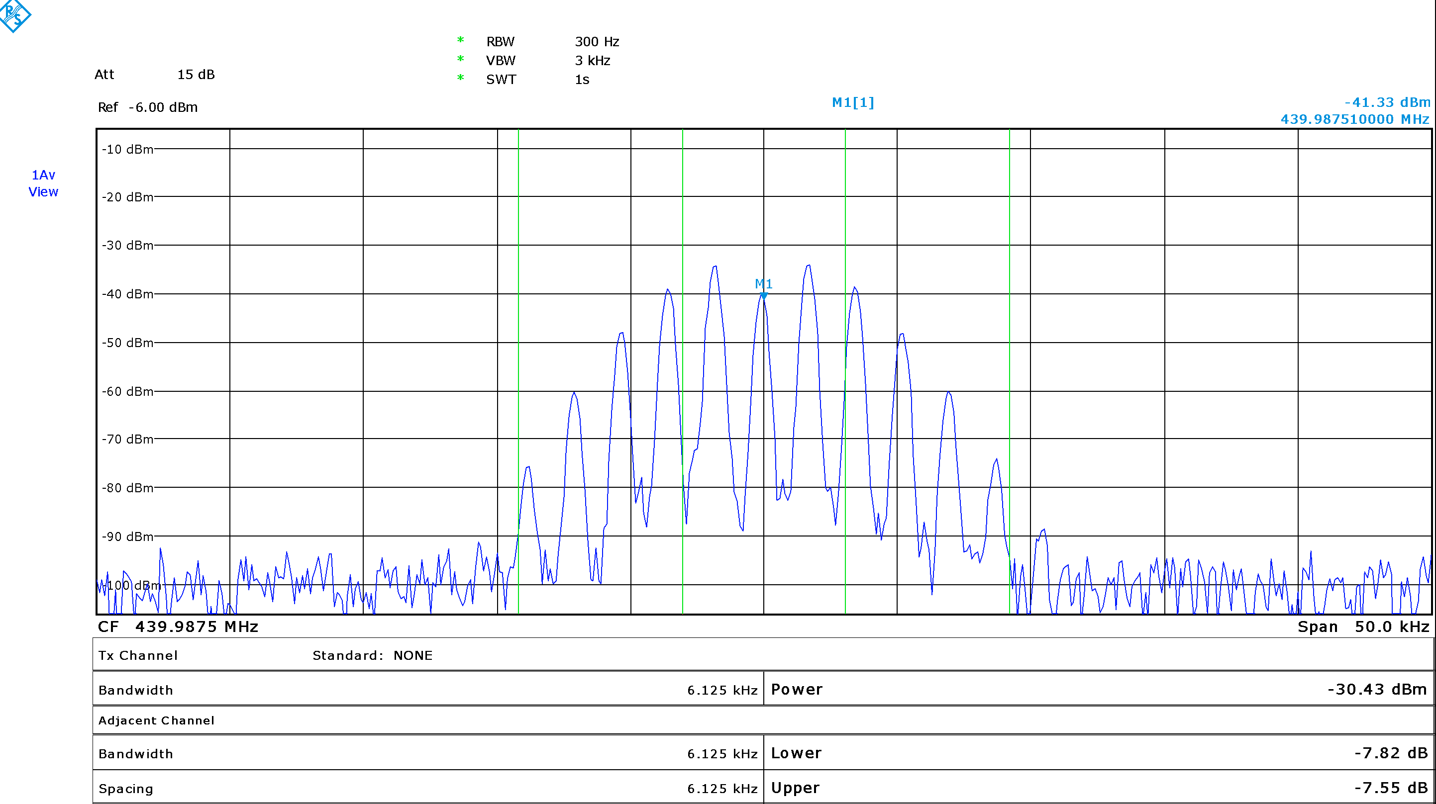
IC-E92 FM wide 1750Hz
FM narrow:
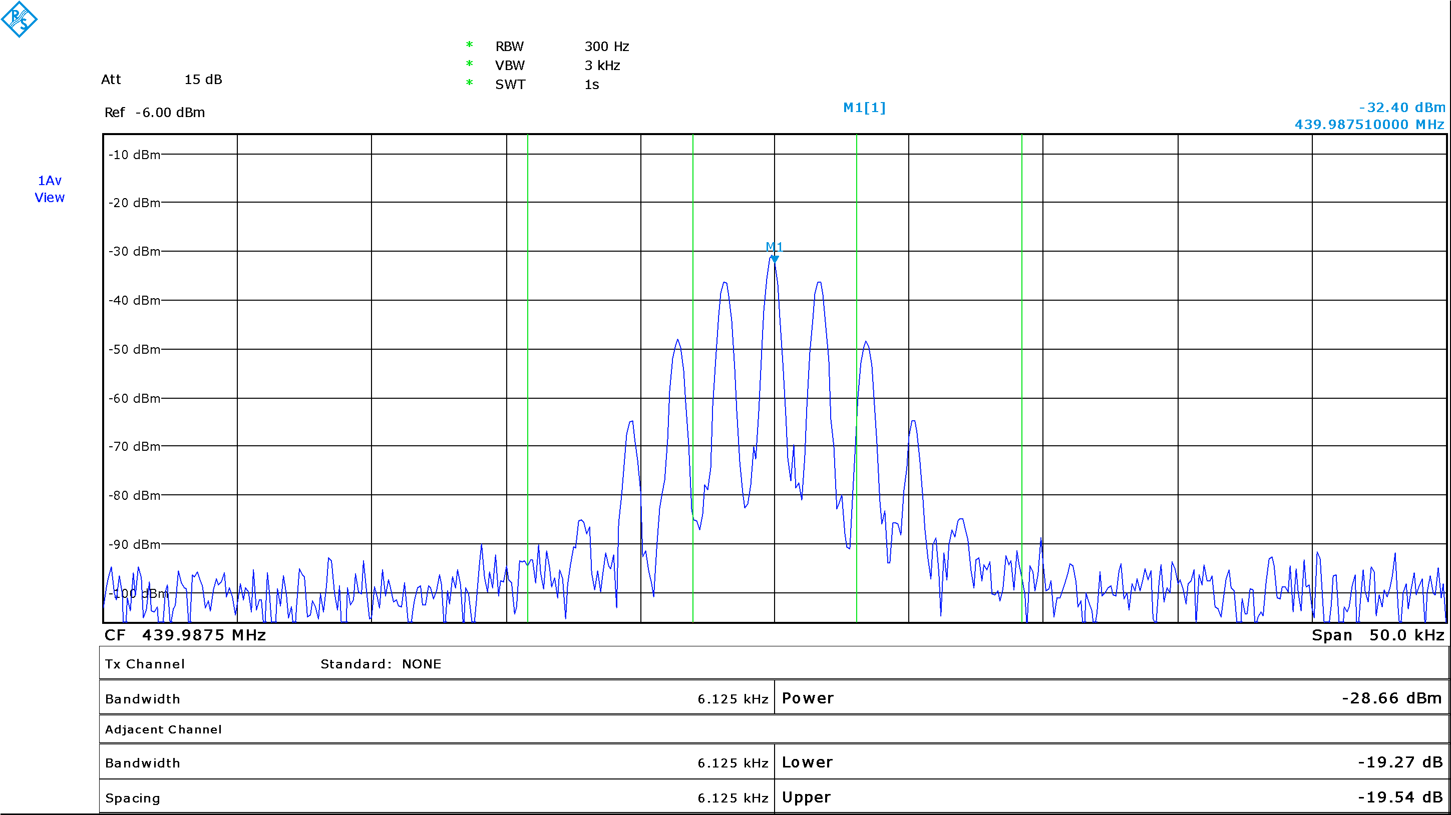
IC-E92 FM narrow 1750Hz
D-Star (only half span screenshot):

IC-E92 D-Star
You can see that D-Star is really the most narrow band mode. Using neighbor frequencies at close QTH still cannot be suggested but at least the interference will be less than for narrow band FM.
Pipe cap filter for 6cm
The picture shows a pipe cap filter experiment for 6cm. The 3/4″ pipe cap filter can be tuned between about 3.4GHz and 13GHz (see below).
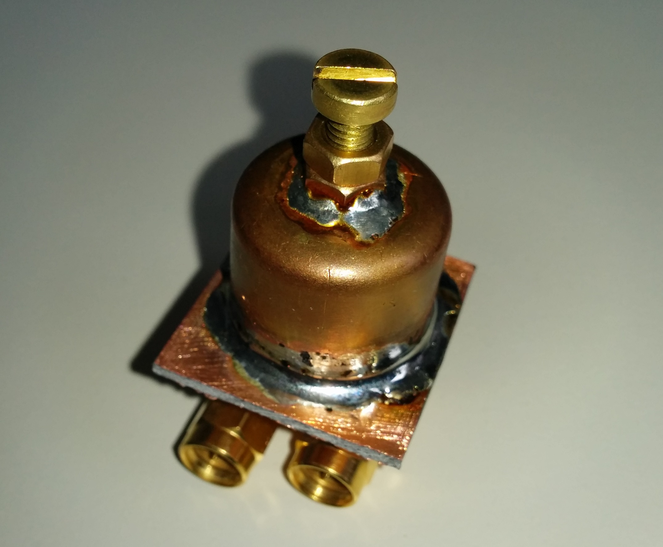
Pipe cap filter for 3.4 to 6GHz range
The filter shown here approximately looks like that (screw is M4, 4mm diameter type):
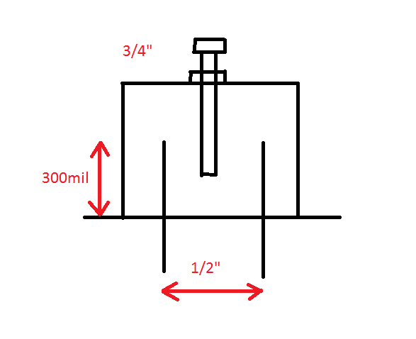
pipecap filter example for 6cm
Some nice paper about constructions of pipe cap filters can be found at W1GHZ.
http://www.w1ghz.org/filter/Pipe-cap_Filters_Revisited.pdf
The measurements show about 0.4dB insertion loss. Do not expect to much suppression. As a simple RX image reject filter or for multipliers its certainly a good option.
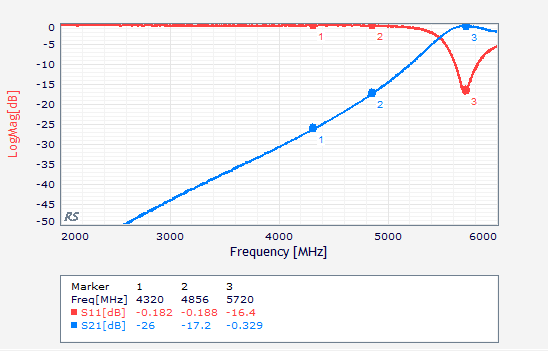
S-Parameter for filter tuned to 5720MHz
However for my construction it seems that the rejection above the tuned frequency is not very good. According to the paper of Paul it seems i have choosen for too long probes.
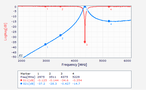
S-Parameter for filter tuned to 4375MHz
[Update1 – wideband measurement]
DL2MRE provided some extended measurement of the filter up to 14GHz.
I have to say, that it looks better than i thought. I was expecting worse suppression at high frequencies due to radiation but it is ok. The resonance at about 13GHz might come from the 90degree SMA connectors. However the bandwith is rather large and has an unexpected shape. Might be some parasitic effect ? Thanks to Marcel !
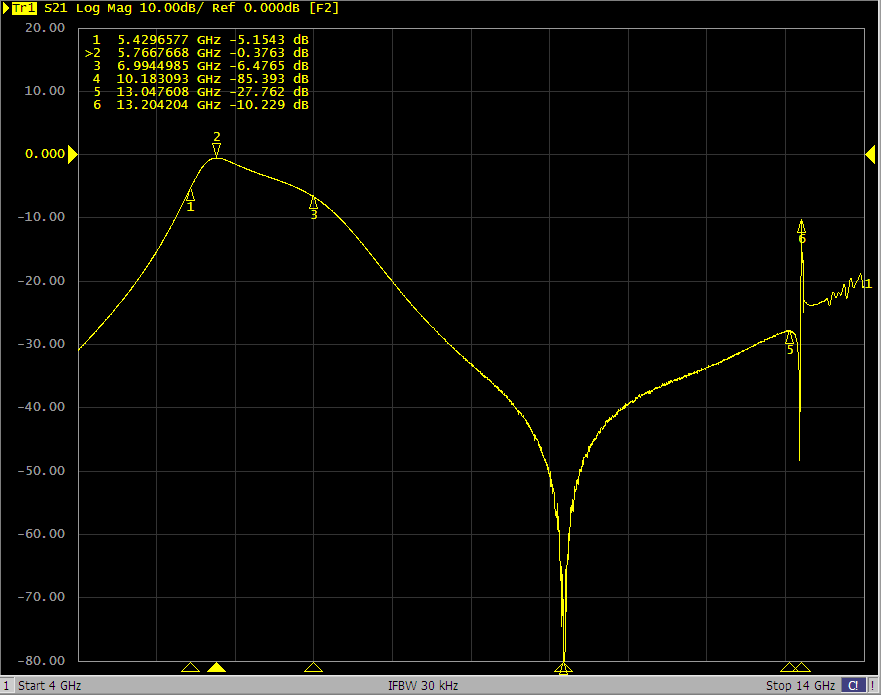
pipe cap 6cm wide measurement 4-14GHz
[Update2 – unwanted response and tuning range]
Marcel made some more pictures with the filter tuned to different frequencies.
It can be seen that there is some unwanted respone of -15dB around 7GHz. This stays more or less static with respect to the frequency the filter is tuned to.
From above you see that the coupling probes have 11mm length. 11mm x 4 in wavelength equals about 6.8GHz in free space. So direct coupling between the probes is the most probable reason.
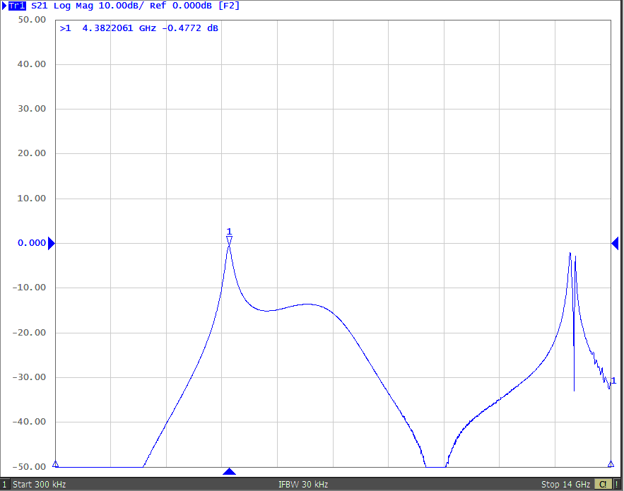
Filter tuned to 4380MHz
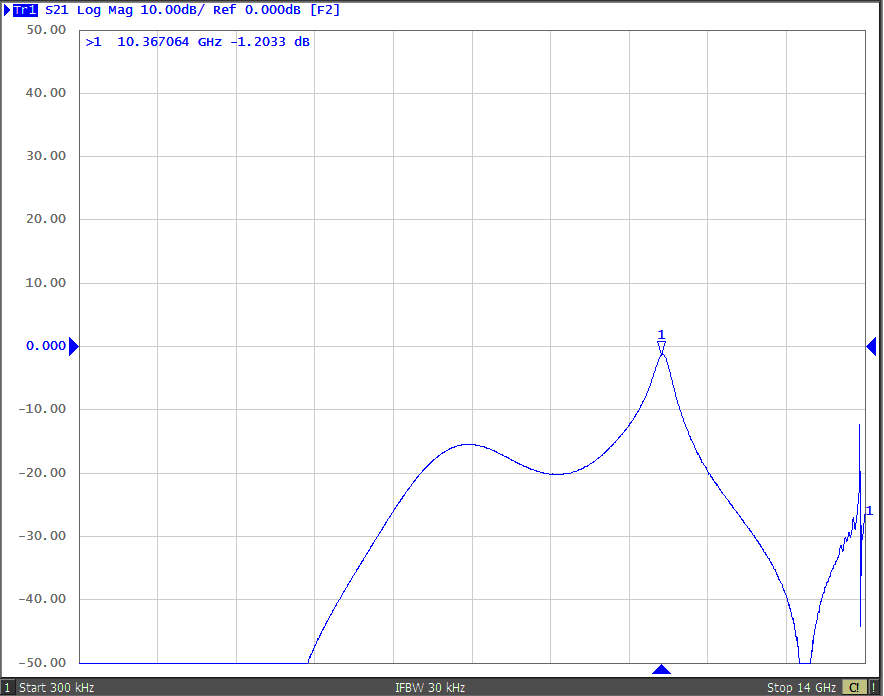
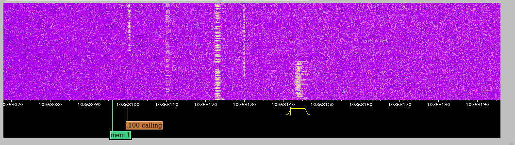
Filter tuned to 10368MHz
Another outcome was that the tuning range of the filter is very large from about 3.4GHz up to 12 or 13GHz.
Because of the static unwanted filter response i decided to open the cap again and shorten the probes to about 5mm (so about 15GHz). As described at W1GHz this has significant impact to bandwith and insertion loss of the filter. Now it is rather hard to tune it to the correct frequency. I will post some measurement results later.
WSJT-X 1.7.0-devel for Odroid U3
For some tests i finally succeeded to compile WSJT-X 1.7.0-devel with JTSDK.
https://sourceforge.net/projects/jtsdk/files/linux/
The documentation seems to differ from what needs to be done slightly. The difference was that i needed to place the jtsdk-xxx directory in my home directory and rename it to jtsdk. I used jtsdk to generate a .deb package. Find it below. Maybe its useful for someone.
I run a small Odroid U3 board with the Ubuntu 14.04.2 image from hardkernel. The board itself is obsolete meanwhile. Maybe the package can run on other ARM boards too.
wsjtx_1.7.0-devel_armhf.deb
I am not sure what dependencies you need. Please refer to the JTSDK readme if you need some guidance.
This is a screenshot of the software. I did not do a qso yet. So i cannot guarantee that it is really working well.
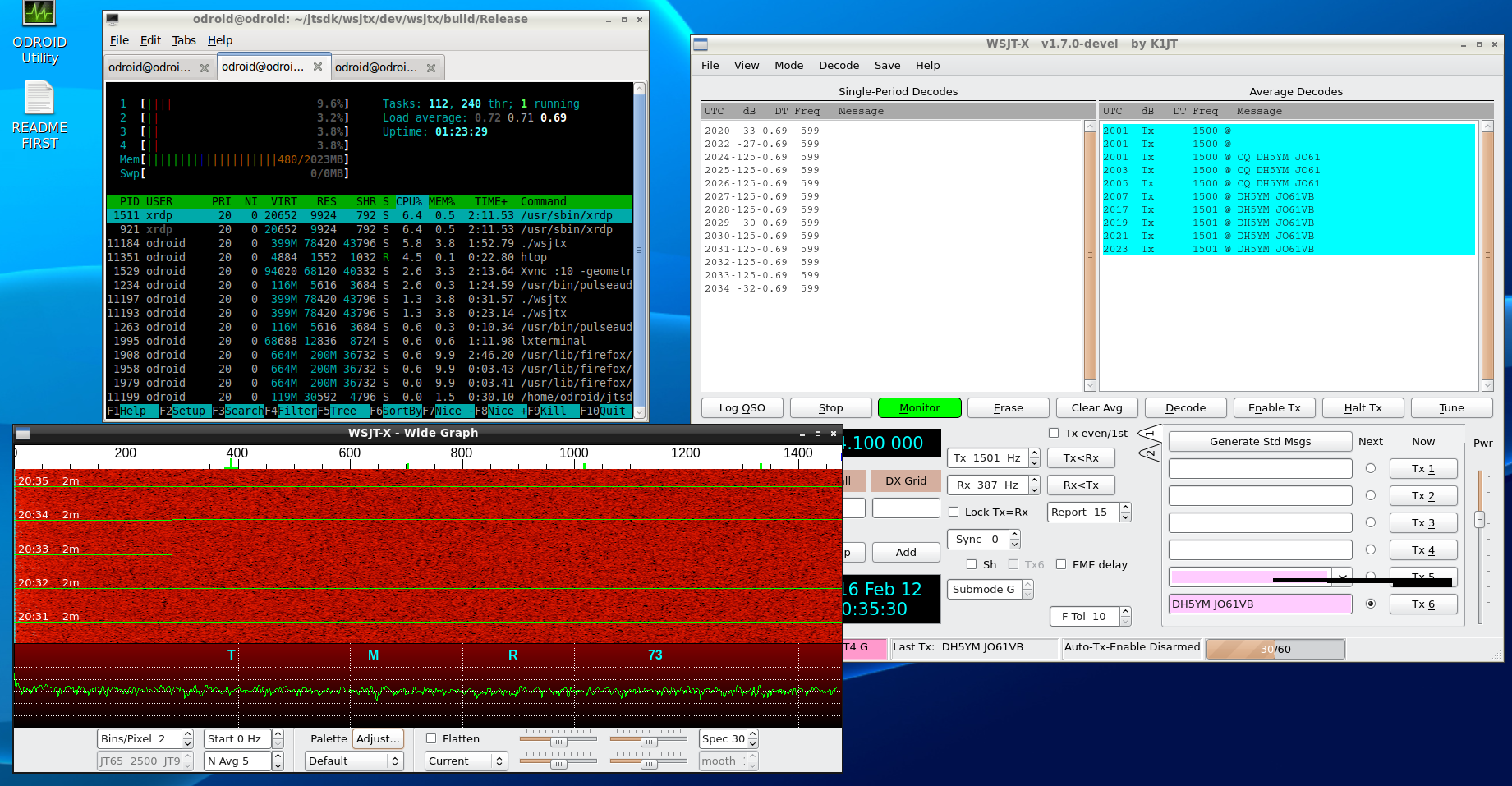
wsjtx-1.7.0-devel on Odroid U3
Attiny2313 based sequence control
Over a year ago i started building a little sequence control unit for transverter usage. The PCB i showed already here. Unfortunately i made a stupid beginners mistake and used a package that does not belong to the footprint. So the first PCBs can be just brought to life with a bunch of patch wires.
Now i found some time to bring the microcontroller firmware to a usable state and made a short video of operation.
Attiny sequencer

The schematic you can find here:
Please notice that the attiny package shown in the schematic belongs to the package without leads which is not the one on the board !
The sequencer has a lowside switch for RXTX relais control and a highside switch for PA supply control as the sequencers from DB6NT have. In addition there is a TX_INHIBIT output that can be used to prevent your Yaesu radio from transmitting until the sequencer has switched to TX entirely. Alternatively you can use it as PTT signal for your transceiver. And there is a kind of “sequencer active” signal that only switches to ground if the sequencer is in TX state (in the schematic its named ERR_OUT but i used it for this function now).
In contrast to other sequencers this one has an error input. If this input is keyed down only the RXTX relais is switched on and the rest of the functionality is locked (means the sequencer cannot switch to TX anymore). It is necessary to release the error input and the PTT to get back to RX state. Together with the “active” output this can be used to lock several transverters against each other for example if they are used with a common dish.
In addition i equipped the board with a ULN2003 darlington array that can be used as 7 port lowside switch to realize further switching outputs.
As i told before a somehow messed up the layout. Thats why i do not publish it here. If there is some interest i can update it to the correct package and make it available. However i show some more pictures of the prototype unit.

top side – LED at the PA output, lamp at the relais output
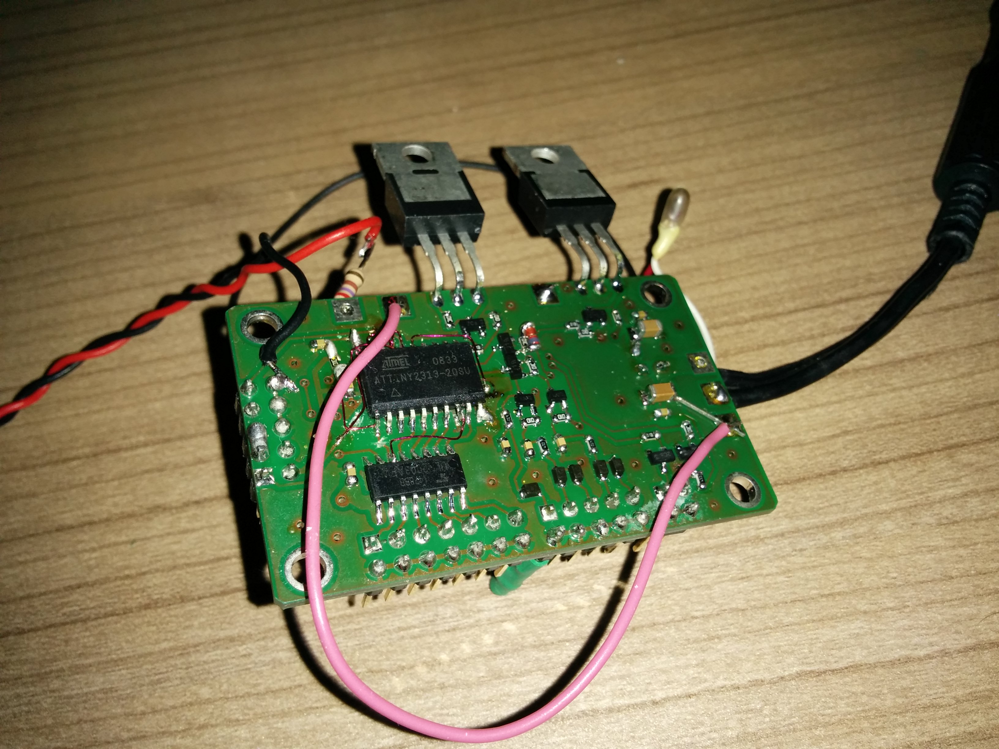
bottom side – attiny2313, uln2003, few transistors, diodes, …
In the second pictures you see the necessary patchwires. Fortunately GPIO are software configurable ;)
Switching behavior is normal for a sequencer. The yellow line is PA relais output, the green line is the PA supply voltage, the blue line is the TX_INHIBIT output. The PTT input signal is not shown here but was asserted from start of relais until the TX_INHIBIT signal goes high again.
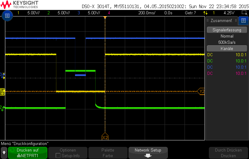
sequencer switching
Further ideas for the circuit are welcome. Some i already got. E.g. controlling rotary RF switches. I will look into that.
MMC2015@JO60TR
Last weekend i was able to participate in the Marconi Memorial VHF Contest. First of all many thanks to DL4DTU and DL3DTS for giving the possibility to use their great QTH in JO60TR together with the antenna group 4x9ele + the amplifier !
I used my HiQSDR already few contests before. Now i wanted to try on 2m as well. I decided to purchase a ME2HT-Pro transverter which perfectly fits the transverter input/output of the transverter. You can see the setup on the picture below.
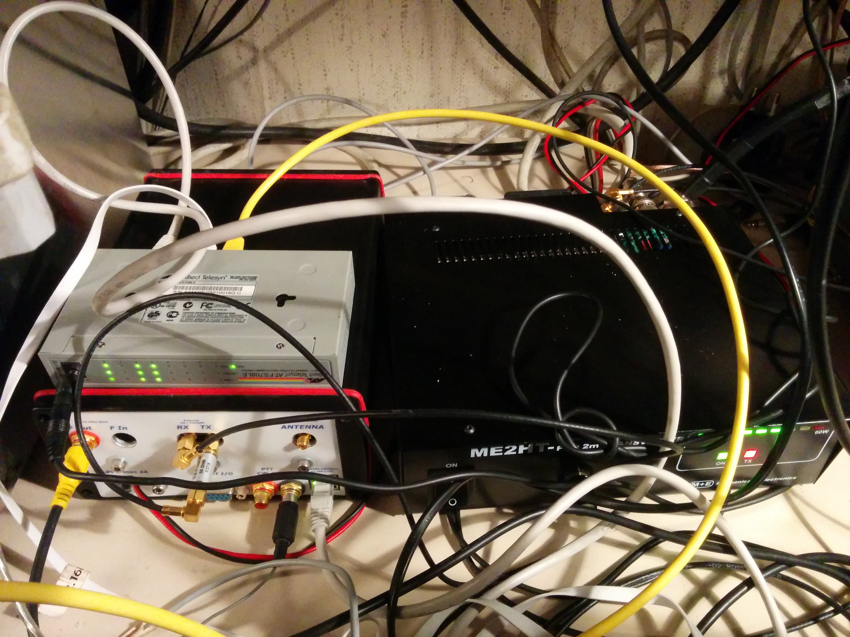
HiQSDR + ME2HT-Pro
The SDR is controlled from the Quisk software. I usually use 196kHz bandwidth setting. This time i tried the CWSkimmer software. Quisk can forward the received baseband samples to a audio loopback device which is fed into the skimmer running under Wine.
The first time i used the very powerful Tucnak log from OK1ZIA. The log got the skimmer spots. In addition also Quisk connects to the skimmer. If the center frequency shifts Quisk tells the skimmer the new center frequency. This is required to always get correct spots. From the bandmap and the cluster window of Tucnak its directly possible to control Quisk like a hardware transceiver. In addition Quisk has a 2nd RX that can be used to listen to other frequencies in between the CQ loops. The picture shows the SDR PC on the right side and log PC on the left side. On request of some OM i also fed the skimmer spots into the reversebeacon network. Sometimes i had the impression that this caused sometimes other stations beeing faster than me ;)
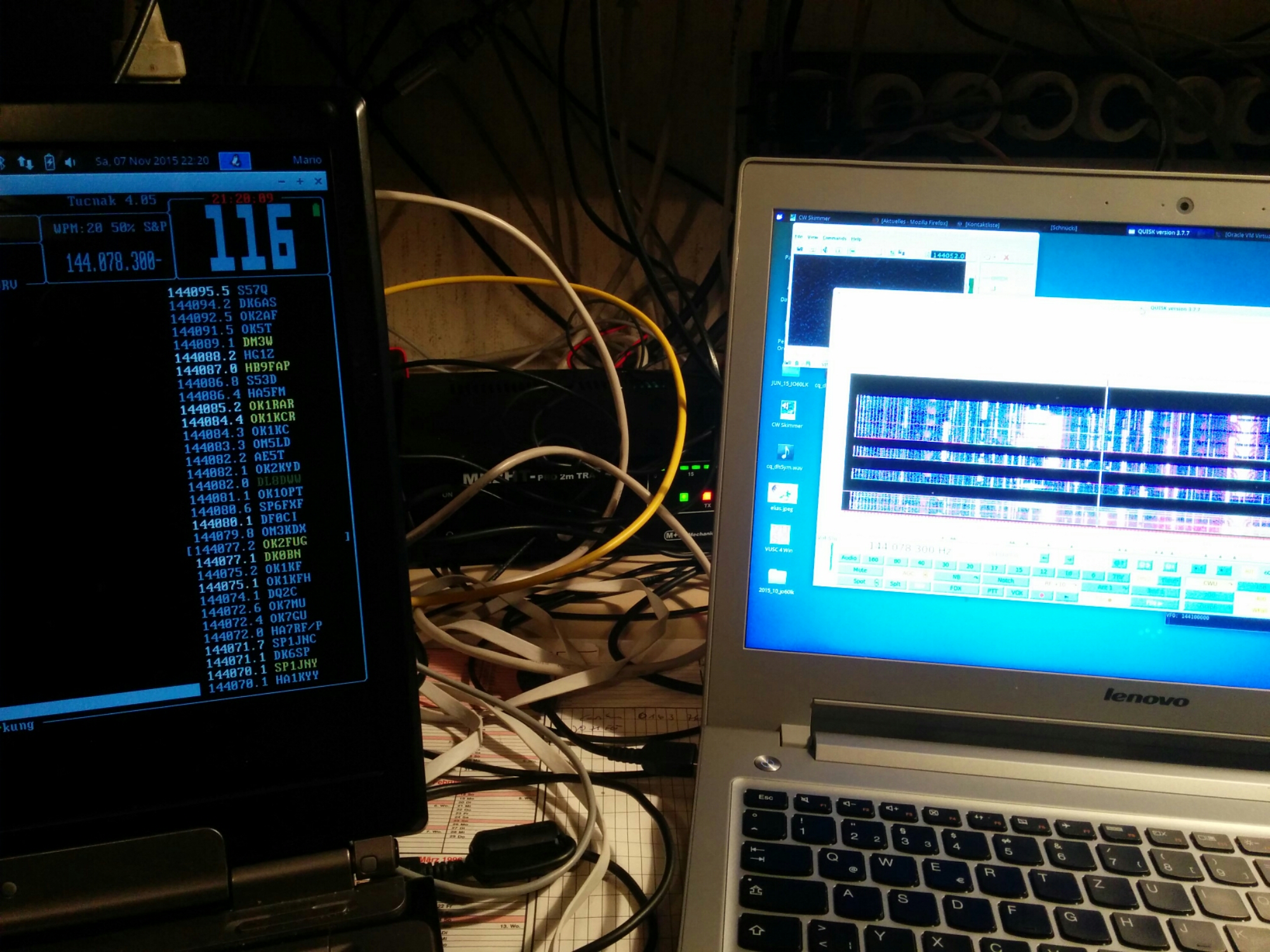
Log and SDR PC in JO60TR
The big advantage of the skimmer connected to the local system was that i immediately noticed when DX stations were heading their antennas in my direction. Looking through the skimmer spots i noticed that i still missed quite some station from DX.
To avoid turning the antenna array all the time i decided to use a second antenna system. In addition to the 4x9ele of Norbert i mounted my DK7ZB-Oblong to one of the other masts at the QTH. The array ran with about 400wtts and the omni antenna with about 200wtts. Reception was selectable from either the one or the other antenna.
Overall the setup was working quite well. The only part that really caused a lot of trouble was the sequencer required to switch the various relais in the correct order. The microcontroller in the setup had problems to keep the PTT. Impulses from the switching relais caused the PTT input of the sequencer to raise for a short moment and afterwards the PTT was not detected anymore. Sporadically my transmissions got interrupted by that effect. Sorry for that. In addition i had some minor trouble configuring all the software correctly since the IP network setup was quite different than at home. I also had to extend my wireless internet access 2 times. One time because the Windows VM with the aggregator software wanted to download a Windows10 update ;)
In the next picture you see the map of the worked stations. The result was about 250QSO and a bit over 80000 points raw score with a average of about 300km per QSO.
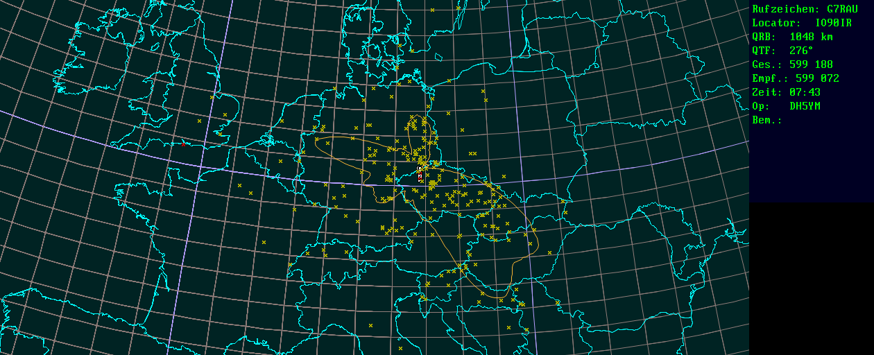
QSO map mmc2015 from JO60TR
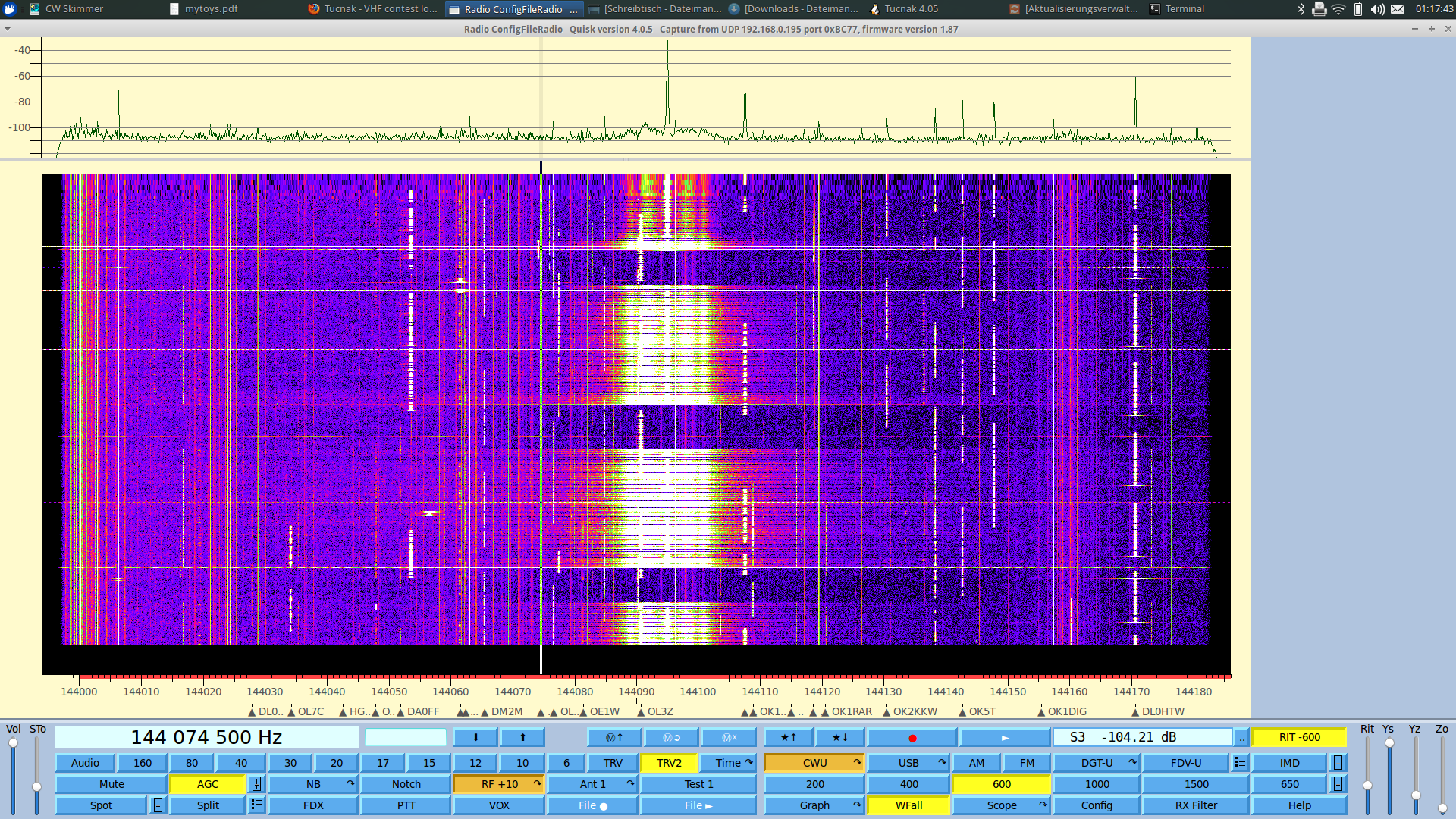
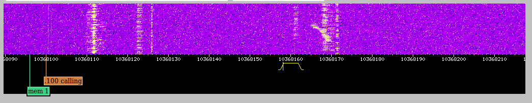
Last but not least i want to show some spectrum screenshots from the contest.
The Erzgebirge is known to have a high density of VHF contest stations from OK and DL. Therefore the band is very full.

waterfall mmc15
Within the waterfall history its a lot easier to find a free frequency than with a normal transceiver. You also see in which direction you need to move if one of the other close high power stations comes too close. For the close high power stations you can also see the problems of the different transmitters that can cause wideband interference.
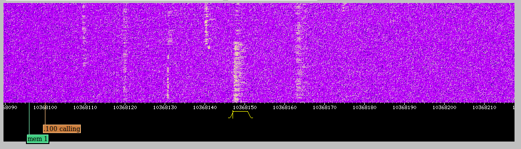
Example 1: Phasenoise of the transmitter
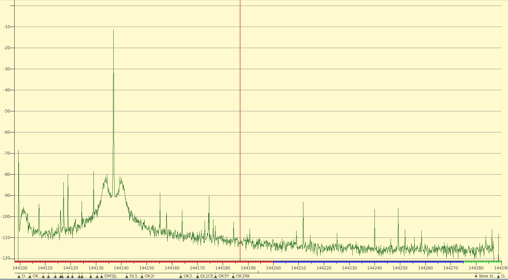
poor TX phasenoise
This is really a poor example since the noise is less than 70dB below the carrier.
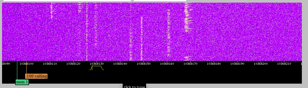
Example 2: Keying clicks causing splatters

keying clicks
In that example the spectrum of the oscillator is a lot better. But the hard keying of the TX causes leakage to other frequencies about 85dB below the carrier. The level was rather low but remember the proximity and the high antenna gain and TX power.
I wonder if someone can give me honest feedback about my own TX signal…?
73 de Mario, DH5YM
Tucnak, Quisk, HiQSDR, skimmer
In preparation for the Marconi memorial contest i tried to improve my setup. I use my HiQSDR with Quisk. Since a few versions Quisk has a built in DX Cluster client. Quisk forwards its baseband samples up to 192kHz bandwith to the skimmer and i managed to send the skimmer/lo_freq command if the center frequency of my hardware changes. The nice thing is that all decoded calls are printed right below the waterfall. The rest is reading the skimmer into the very nice and powerfull Tucnak log of OK1ZIA. The software mainly is a log for VHF/UHF/SHF contest operation. Lada also implemented a nice new feature. Now its possible to zap through the calls in the bandmap with ctrl-arrow and Quisk is automatically controlled via Hamlib. Further features of Tucnak are integration of ON4KST chat, airplane scatter prediction, cw keyer, ssb keyer, recording of all contest audio and a lot more. It can also work in environments with multiple stations connecting several Tucnak logs together. Available for Linux, Windows and Android.
UHF/SHF contest JO60LK
QRV from JO60LK on 23cm. The picture shows the setup. The HiQSDR was connected to the 23cm to 29MHz transverter. The Quisk software runs on my i7 notebook. On the same machine i ran Airscout and a client for the ON4KST chat. The notebook below runs the VUSC log under Linux in Wine. The log features a CW keyer which connects to the transceiver via the interface box in the middle. The rotator control at the left side can be controlled from VUSC as well and direct the antenna towards the locator entered.
The output power was 2x100W with 1.5m dish and Quados 8.
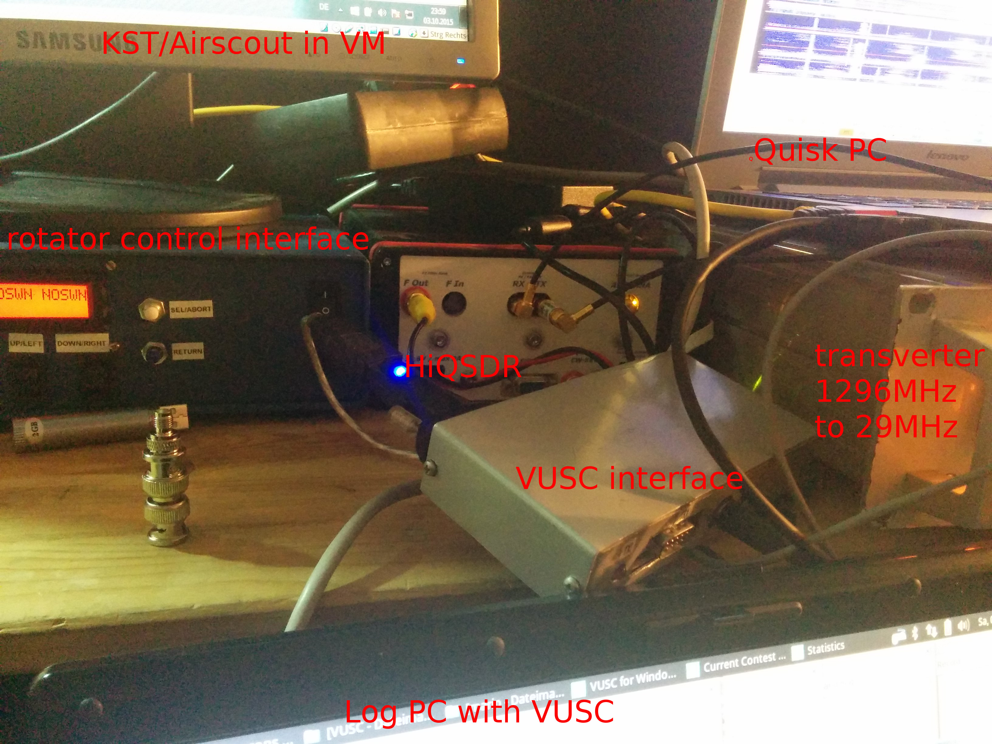
OCT15_HiQSDR_Setup
Two recordings:
PI4Z – 648km
PA6NL – 639km
Rainscatter 20150704 July contest on WebSDR
Saturday evening there were strong scatterpoints west and northwest of Berlin. Since the same time there was the July V/U/SHF contest this gave amazing scatters from the contest participants. I listened with our local 10GHz websdr and did some recordings and screenshots. Please see below…
Stations heard were:
DL6NAA, OK2A, SN7L, DL0GTH, DL1SUZ, DL0LN, DJ1LP, DM2EUN, DL9GRE, DF0XX, DK2ZF/P, DL3YEE, DC6UW/P, DC7BQ, DG6ISR, DL0VV, PA0BAT, DK7QX

![]()