A small VHF/UHF driver

I was searching for a small driver for 2m in order to have enough power for my microwave transverters. I usually drive them with about 500mW. Since i have a transverter block with about 0dBm output it needs some gain. Again i found something from China. The advertisement told something about 1.5W, the pictures showed a PCB with a print 35dB/3.2W. However, i thought it could be good enough to get 0.5W out of it.

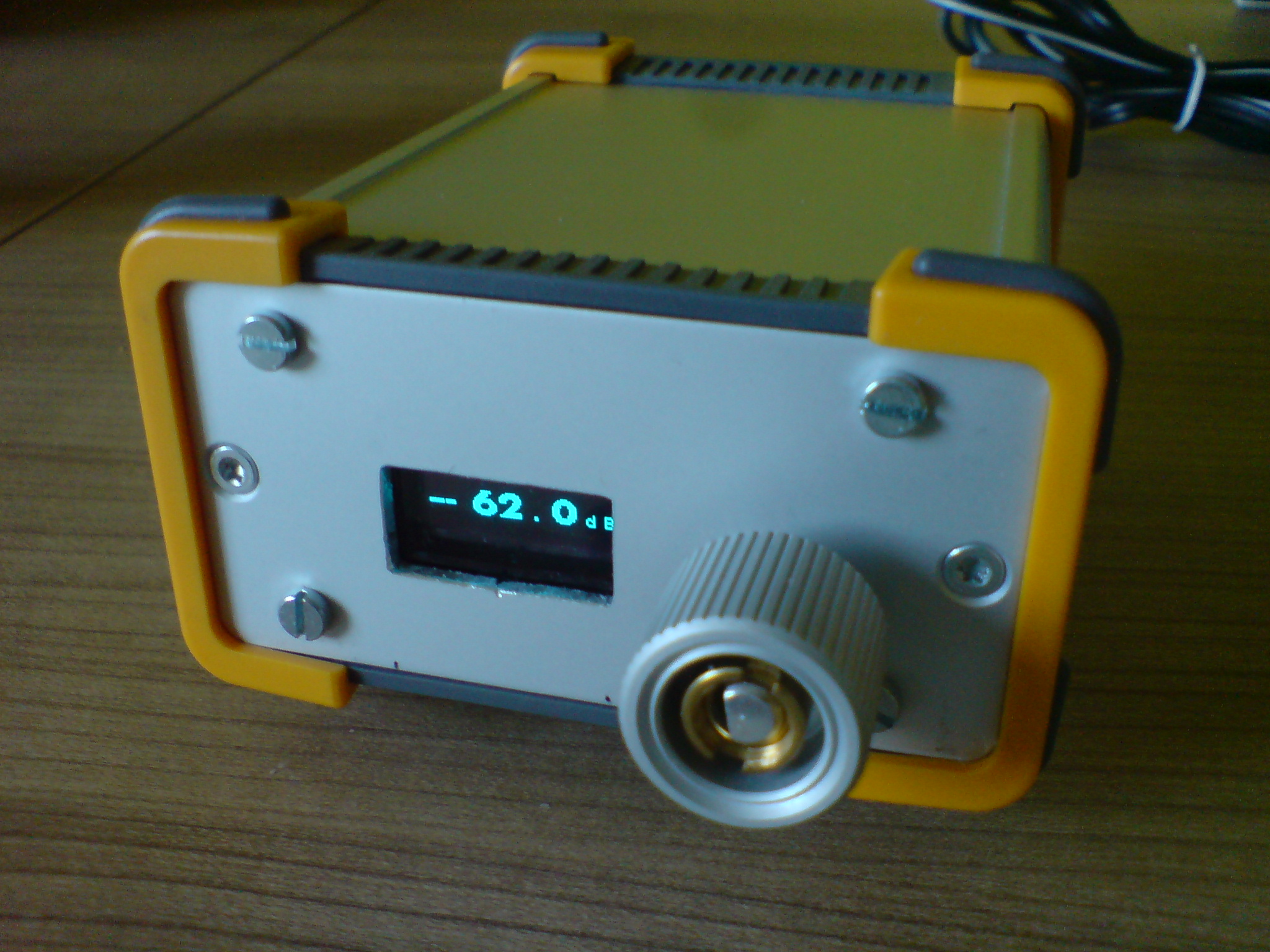
A small VHF/UHF amplifier


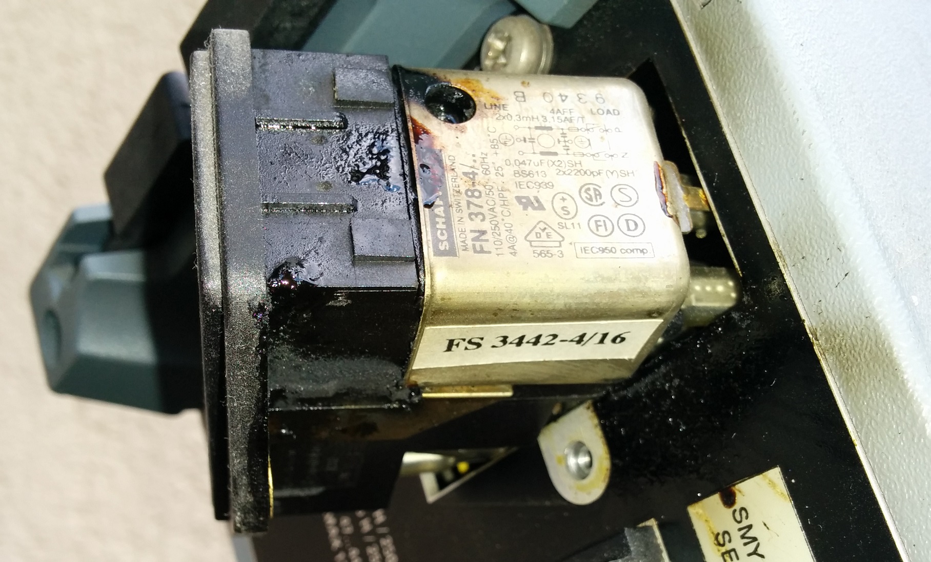
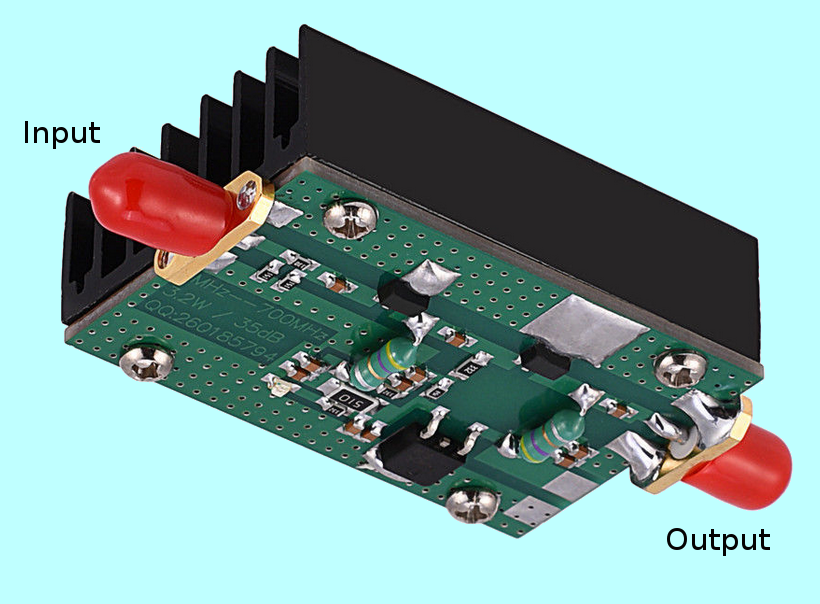
When the device arrived i noticed that the manufacturer milled the top of the two amplifier IC. Very funny that the guys there try to save their designs from unwanted copy ;)
At the input there is a 6dB attenuation pad which are followed by two amplifier stages of unknown type. The first stage is supplied via a 5V regulator, the second one is connected to the supply input directly. I used 12V to do some measurements.
The first action was to know the gain of the circuit. I wanted to see if it is really working from 1 to 700MHz.
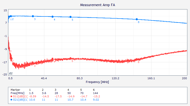
In the picture you see the little noisy measurement. The drive from the analyzer was set very low.

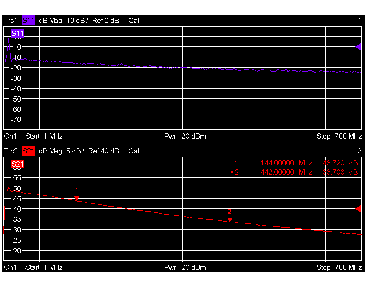
Gain of small VHF/UHF PA


From the gain curve it can be seen that the device is probably not working that well at the lowest end of the shortwave. But at least from 30MHz on it should be usable. Towards upper frequencies the gain is decreasing a lot but still 27dB at 700MHz. For the 2m band roughly 43dB gain is achieved and about 33dB in the 70cm band.
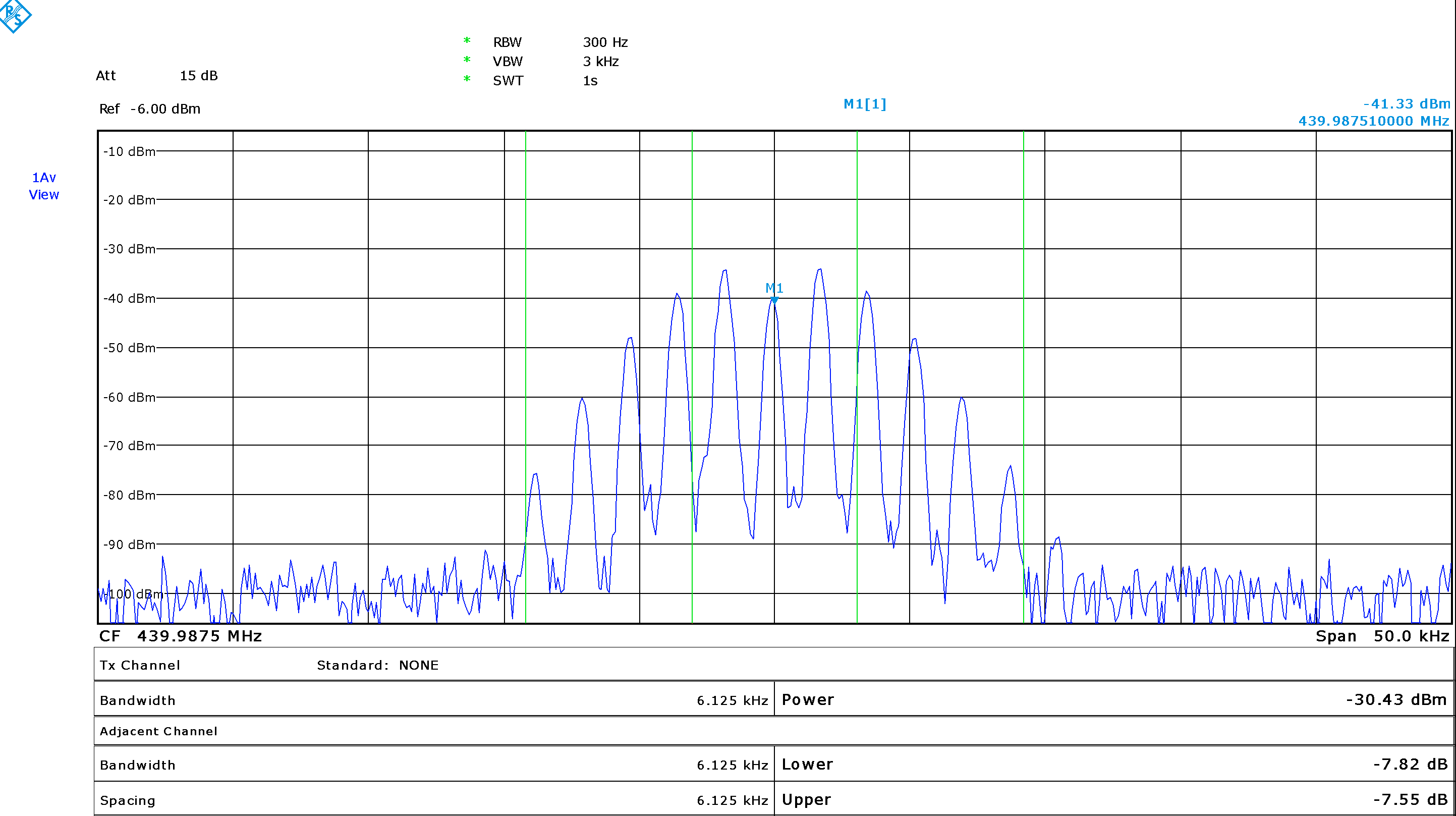
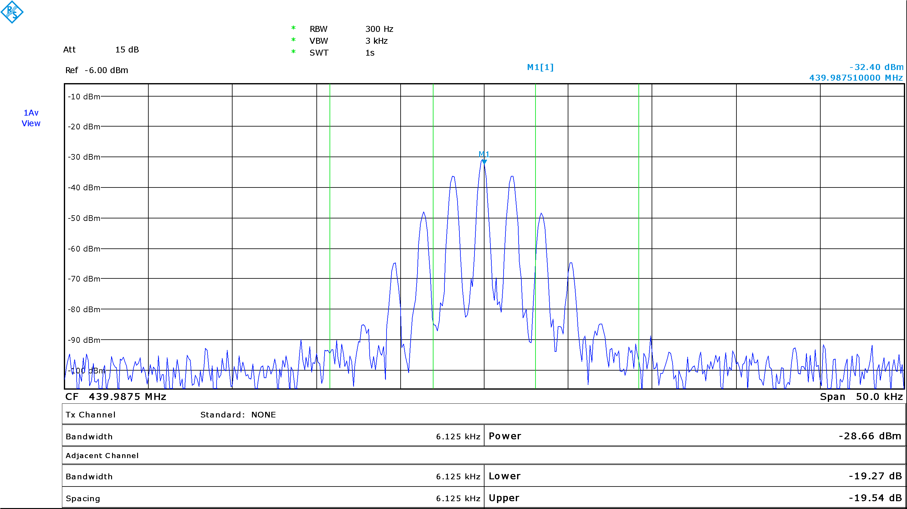
Finally i wanted to know which output power can be achieved in the amateur radio bands.

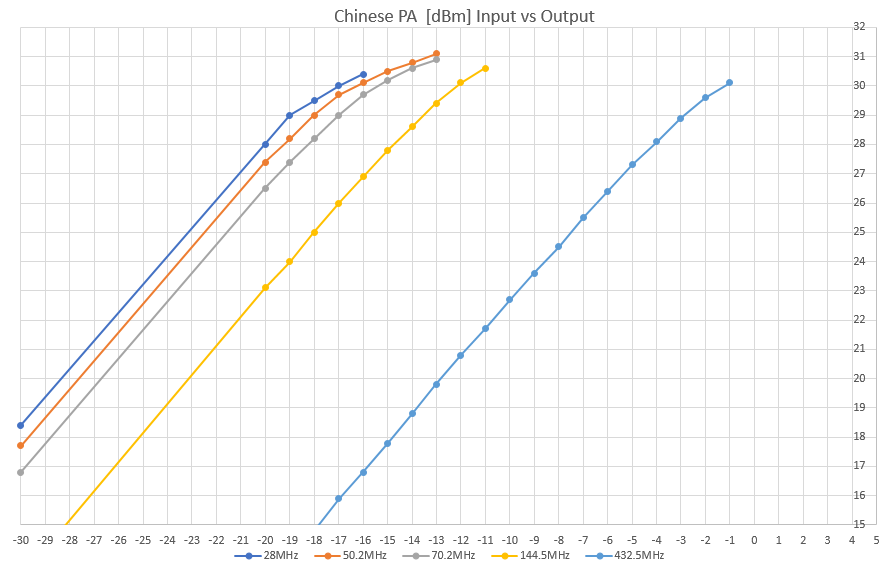
VHF/UHF PA output power


At about 1W output the output always gets compressed. You might add about 0.4dB on 70cm and 0.3dB on 2m to my measurements since the graph does not include the attenuation of the output cable. For me it means that the amplifier should work well for my purpose.

Wideband amplifier

I tested my new assembled wideband high IP amplifier (BX-088) from Funkamateur. The transformers need to be handmade which is a very fiddling task. The cores are really small. I choose for 11dB gain assembly. The measurement shows, that the gain really rapidly drops below the 160m band. The figure fits to what is shown in the documentation. So far i did not measure the p1dB or IM3 behavior.
The points that are interesting for me are 28MHz as LNA for my SDR or as IF amplifier for transverter input on 14/28MHz and usage as pre-amp for 70MHz.

Measurement of Funkamateur wideband amplifier

Burned mains filter

Last weekend i had a negative surprise. Some noise from the desk and a lot of fume indicated that some electronic stuff burned.
Investigating the source of the fume i found that the mains filter of my old R&S SMY-02 burned away.
Fortunately i have connected it to a switchable mains distributor which prevented it from burning in my absense.

burned mains filter of SMY-02

burned mains filter of SMY-02

IC-E92 spectrum

Triggered by some forum discussion about interference risk of operating repeaters in neighbor channels in 6.125kHz channels I was curious about the TX spectrum of my IC-E92. The measurement was done radiated. I checked for neighbor channel interference. You can see the delta values bottom right.

FM wide:

IC-E92 FM wide 1750Hz

IC-E92 FM wide 1750Hz

FM narrow:

IC-E92 FM narrow 1750Hz

IC-E92 FM narrow 1750Hz

D-Star (only half span screenshot):

IC-E92 D-Star

IC-E92 D-Star

You can see that D-Star is really the most narrow band mode. Using neighbor frequencies at close QTH still cannot be suggested but at least the interference will be less than for narrow band FM.

62dB step attenuator by SV1AFN

A nice page and a source of some good projects is the one of Makis, SV1AFN.
The page can be found at sv1afn.com.
I purchased the step attenuator control module with 2x 32dB attenuator blocks. The both blocks can either be used in parallel always set to the same attenuation level or in series allowing a maximum attenuation range of about 62dB.
Build into a small enclosure it gives a really nice unit for your daily usage.

sv1afn step attenuator - front

sv1afn step attenuator – front

sv1afn step attenuator - rear

sv1afn step attenuator – rear

Converting from Virtualbox to VMWare / Get DG8SAQ-VNWA working in a VM

I tried to get my DG8SAQ-VNWA working on my Linux laptop in the Virtualbox WinXP machine. Unfortunately i found that there seem to be a lot of problems with loosing samples of USB sound devices within Virtualbox. This problem is reported at several points. For the VNWA this means it is not possible to calibrate the samplerate. Loosing samples means noisy traces and not doing proper measurements at all.
In the Yahoo group it was reported that it works under VMWare. So i thought i give VMWare a chance. Some information in the internet state that it should be relatively easy to export from Virtualbox to OVA files and import into VMWare. Unfortunately my VMWare always crashes when importing the OVA file. It seems the metainformation of the VM is not written or imported in a compatible way although this is defined in an open standard (whatever this really means).
After 3 days of experiments i found a solution. Now within VMWare the audio is working and i get perfect traces from the VNWA.
The way to convert was:
– uninstall the Guest extensions within the guest system when running Virtualbox
– export the VM using the OVA 1.0 format and write separate files (specify ovf file ending and you will get the vmdk file separate), 2.0 did not work.
– use the ovftool with option for relaxing the check for errors in the ovf file, otherwise ovftool will stop because of unknown identifiers.
for example ovftool –lax WinXP.ovf WinXP-vmware
– Import the newly created copy by importing the vmx file

After that i was able to boot the VM, start the software, recalibrate samplerate, calibrate, measure.
The version number of Virtualbox is 4.3.6 and VMWare 6.0.1.

Measurement of coil saturation and inductance

A nice document that describes the measurement of saturation current of coils and calculating the inductance can be found here:

Attention !! This is an external link, i am not responsible for the content !
http://staff.ltam.lu/feljc/electronics/messtechnik/messung_ferritspulen.pdf

Jean-Paul Feltes wrote a very nice description about how to do it and what needs to be considered. Unfortunately it is in german language only.
This is a picture of a measurement of a selfmade coile with a ferrite core purchased from a big german distributor.
Unfortunately the exact parameters of the core and the air-gap are unknown. Since i have some problems with the saturation of the core in a switched power supply i tried to measure.
The inductance matches what i measured with the network analyzer. The saturation of 2A appears to be quite low. Probably the inductance is choosen too high.
In the picture you can clearly see the point where the coil gets nonlinear because of decreasing inductance when saturating.
Be careful not to switch on the transistor for a too long time and care about sufficient time to get the coil voltage to 0.

Saettigungsstrom

saturation current and switch signal for the transistor

TQ2SA relais for RF switching

I tried a cheap TQ2SA SMD relais for RF switching. The circuit was using the 2 switches as one SPDT switch with the unused output connected to ground.
Find some pictures attached. For low power it should be possible to use the relais up to 70cm (ok, 30dB isolation only). On 2m and below it works with good results…

relais side

relais side

connector side

connector side

TQ2SA-5V_SPDT_insertion_loss

TQ2SA-5V_SPDT_insertion_loss

TQ2SA-5V_SPDT_short_crosscoupling

TQ2SA-5V_SPDT_short_crosscoupling

HiQSDR as VNA

Since today the HiQSDR or the original N2ADR frontend might be used as a vector network analyzer for the shortwave range.
Jim wrote a simple tool that displays amplitude and phase between TX port and RX port and can handle some calibration.
Currently it is quite simple and i do not have provisions to measure reflections yet, so i can just measure S21 at the moment.
But for the future it will be a nice feature to have the antenna analyzer built into the transceiver itself.
The picture below shows a simple ugly-style lowpass filter.

HiQSDR as VNA

HiQSDR as VNA