
My rotator control unit (design by DL1DBR) is more or less finished now.
All the stuff is in the enclosure and working. Items that i needed to solve were:
– deal with some bug in the PCB print were the names for the connectors for Keys and LCD are mixed up ;)
– connecting the KR600 rotator which is 24V AC with end switches which needs two driver PCB in parallel to keep this function
– change the connection of the poti in the rotator unit to measurement voltage over the complete 500 Ohms
– change the software to allow for stopping the motor in the moment the direction key is released (before it stopped only on pressing the OK button)
– changing some libraries to get it compiling in my environment
– deal with the CDC UART (i replaced the CDC done with Attiny2313 by a FTDI UART-USB converter, this works in all environments in contrast to the CDC)
– search for a suitable 24V AC power supply for the motor
– get the DC for the controller working in the environment with the motor (i decided to spend a 2nd trafo for the logic because that was the fastest way to get rid of the interference which disturbed all the resistor measurements)
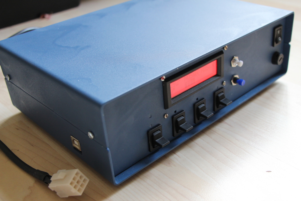
Rotor Control unit DL1DBR
The following picture shows the inner of the rotator control unit.
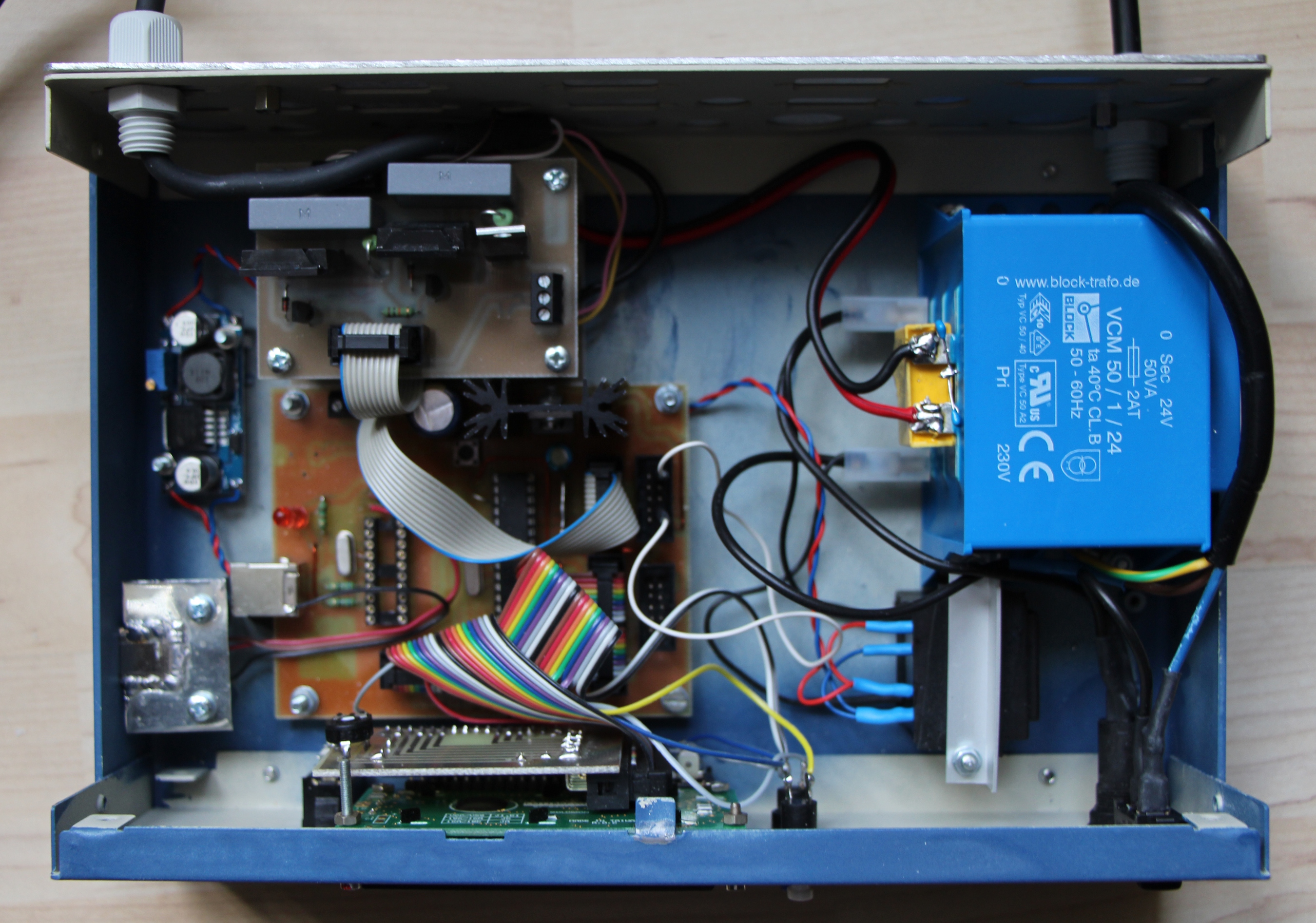
Inner of Rotator control unit
Starting with the right upper edge: Thats the 24V AC transformer that supplies the motor of the rotor unit. Below that there is a small black part. Thats the 15V transformer that generates the voltage for the digital part. Using the 24V from the motor supply resulted in crazy measurements due to the strong interference from the motor. At the lower edge you can see the display PCB mounted to the frontside of the enclosure together with the keys. Above there the brown PCB is the main control unit that is driven by a Atmega controller. It gets its supply from the blue PCB on the left edge of the enclosure which is a DC/DC converter that generates about 8.5V out of the voltage from the black transformer. The PCB above the controller PCB is the driver for the motor. Actually its two identical PCBs stacked. The capacitor for the phaseshift of the motor resides in between this stack. The PCBs use each two solid state relais for switching the supply voltage.
For the remote control of the unit i replaced the Attiny CDC implementation by a FTDI USB-UART adapter that is mounted at the left side. Its the silver part there.
In case you have questions… Let me know.