Since i needed a very lightweight antenna for 70cm for my fibre mast i looked at the Quadlong antennas published by DK7ZB. I downloaded 4NEC2 and started playing around. I simply entered the VHF version and scaled it to the available materials and 432.2MHz. To be honest i dont have a lot of knowledge about this simulation tool but the result looked promising. So i added extra segments at the upper and lower end of the antenna and rescaled it to get proper matching again. The result was promising again. >1dB more gain then before. I made the antenna from 4mm brass material for the horizontal elements and 1mm copper antenna wire for the vertical elements.
Some drawings of the VHF version you can find at the webpages of DK7ZB.
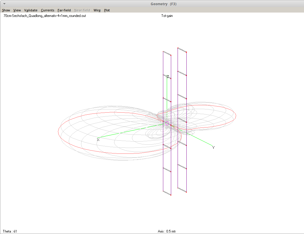
Thats what 4NEC2 shows (ask me if you need the NEC file)
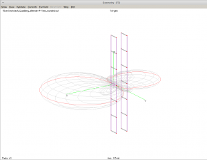
70cm Hex Quadlong drawing
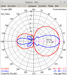
70cm Hex Quados pattern by 4NEC2
BTW i dont trust the gain calculations of 4NEC2 at this stage. I did not simulate with another tool. Let me know if you do so. I can provide the NEC file i created. Just drop me a line and i send it to you.
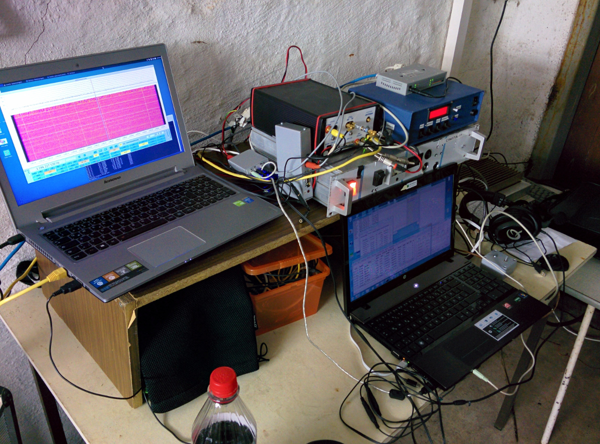
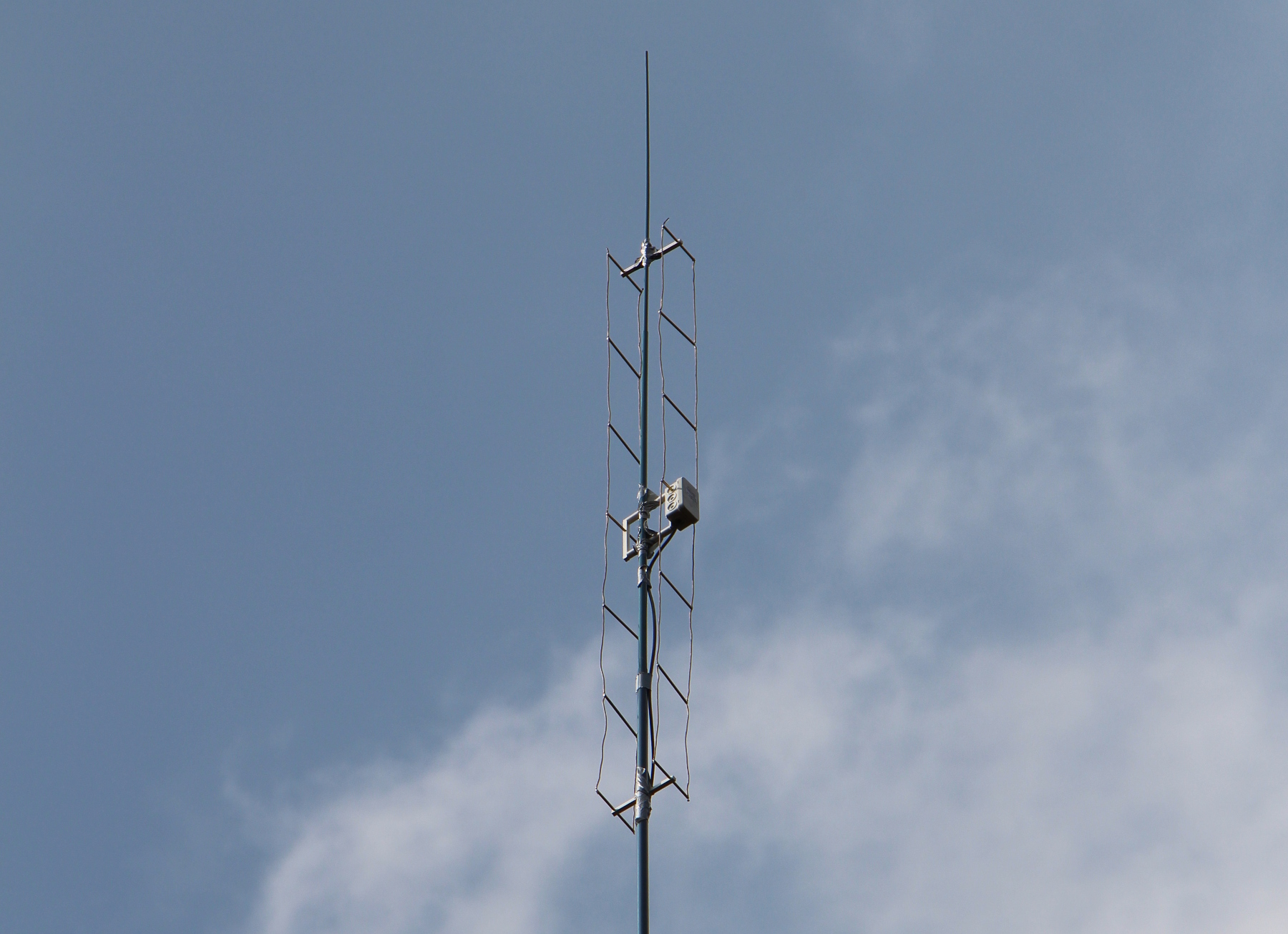
Thats a photo of the antenna as i used it during the UHF contest:
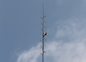
Hex-Quadlong 70cm
Since i finshed when the UHF contest was already started Saturday i decided to glue the antenna to the mast by means of tape. VSWR showed not too good result on 432.2MHz. Tuning few MHz forth and back gave the impression that the resonance was too high.
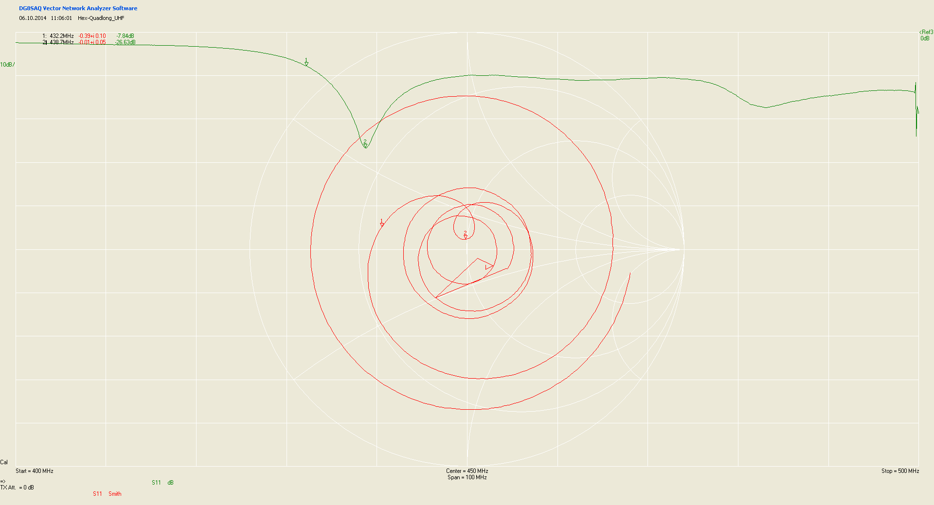
Monday i had a look with the network analyzer. Indeed the resonance is about 6.5MHz too high. Thats how the measurement looked like:
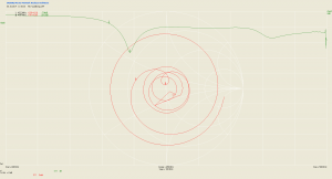
Hex-Quadlong 70cm measurement
Maybe i will do a slight rescaling of the vertical elements to shift it a bit down. Also the mounting needs to be improved.