
2m transverter from Hungary. Working in combination with the Hiqsdr…

2m transverter from Hungary. Working in combination with the Hiqsdr…
I want to run a temporary 4m WebSDR. The software comes from PA3FWM and there is a binary for raspberry pie computers. The binary can run on any ARM CPU. I purchased a Odroid U3 which has a lot more CPU power. The picture shows the Odroid as well as the rtlsdr connected and a wifi stick used for connecting to my network. Running the WebSDR with 1MHz bandwith gives about 50% CPU load.
The board runs Lubuntu 14.04.2. I did not measure the current consumption on the 5V supply.
My aim is to put it in a box to the balkony.
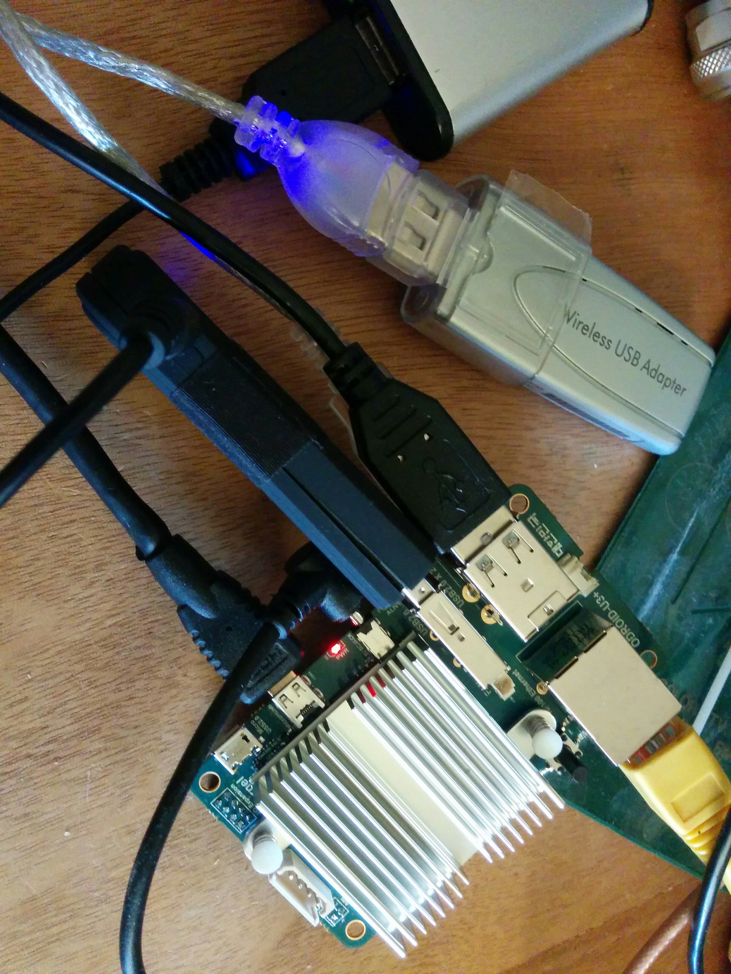
Today i heard my first station on 4m with that setup. SV2JAO.
For some tests with WSPR i purchased a DDS PCB from Kurt DJ0ABR. The PCB comes with most parts assembled and you just need to solder some easy stuff as well as mount it into an enclosure. There is a microcontroller that interfaces with a PC or operates the DDS alone. It can be used as synthesizer for AM FM, as a wobbler unit as well as beacon for WSPR, CW and DSTAR. Frequency range is from medium wave to 160MHz.

Edit:
Today i added the GPS receiver and connected the DDS to a Outbacker 1899 antenna placed on the heating inside the room. During the sunset some stations received my 50mW signal on 20m.

wsprnet_20m_50mW
[The list is a screenshot from WSPRNET.org]
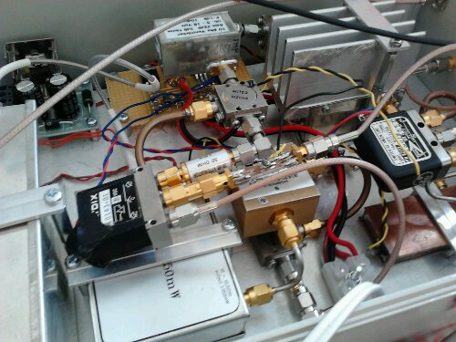
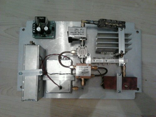
A while ago i destroyed the RX input amplifier of my HiQSDR. Last weekend i replaced the two hittide switches and the differential amplifier of that circuit. Now its fully operational again. On the photo you see the backside of the HiQSDR enclosure as well as my antenna tuner and the SWR/Power meter. The transceiver itself does not have any human interface. It just has inputs for power, RF, key and PTT and outputs for RF, PTT and some control signals.
The digital baseband goes via UDP connection to the SDR PC. Usually i use my Laptop connected via Wifi.

Some days ago i found a nice video clip from an italian guy who used a cheap DVB-T stick (RTLSDR) in combination with a crystal stabilized sat-TV LNB for some 10GHz hamradio experiments.
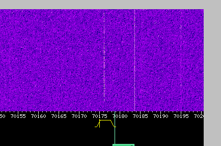
A short search brought up a nice paper about some investigations of G4JNT who investigated the frequency stability and phase noise of one of such LNBs and found that it could be used for narrow band reception in amateur service. It can be found here: http://www.g4jnt.com/PLL_LNB_Tests.pdf Since i already have some experience with the RTLSDR stuff and currently experimenting with 10GHz as well i decided to give this ultracheap setup a chance. I purchased a LNB (which was told to have crystal stabilization) for about 7 Euro and made a phantom feed for that. With just the 12V applied to the coaxial cable it works in the lower band and the polarization is in the direction of the antenna connector. 10386MHz falls to about 618MHz since there are no sharp filters inside the LNB it is possible to receive some ham signals.
The picture shows the reception of the local beacon DM0TUD. Its not very strong here since it comes in via reflection at the other side of the city. With my 60cm dish its about S8. The LNB i use without any dish just placing it onto the cupboard.

LNB + RTLSDR receiving DM0TUD on 10GHz

crystal stabilized sat-LNB
Find here a short video that give an impression how it sounds like.
https://www.youtube.com/embed/SJlcb0t2GGw
The signal sounds a bit ugly because of the LNBs oscillator phase noise. The frequency of the LNB was quite stable after half an hour of operation. The LNB was just lying on the cupboard and used as it is without any dish. I have no direct line of sight to the beacon and i receive the signal just via reflection at the other end of the city. Therefore you can notice some fading.
Edit: When opening the LNB i found that it has DROs and not as advertized on the package a crystal stabilized oscillator. For DROs its working quite well but since its stated even on the package that it should be “crystal controlled” its obviously a fake.
Edit 2: Today i received another LNB. Its a Octagon Optima model OTLSO as measured by G4JNT. I made a new video of the reception of the DM0TUD 10GHz beacon under the same conditions as before. The sound is perfectly fine now.
Now it is almost finished. Just the rxtx switching via the if cable from the trx is not working yet.I need to modify that…
Recently i purchased a cheap RTL2838+ R820T device from a vendor from Hongkong.
The cost was about 10 Euro including shipping.
The video shows some reception with the SDRSharp software.
Tuning range is from about 24MHz to about 1750MHz. I discovered no gaps so far.

In the CQDL edition of Nov. 2012 there was an article about a SDR software called SDR# (SDRSharp). This tool can work with the cheap so called RTLSDR sticks (for example Noxon DAB sticks and others) and runs under windows and because its written in C# under linux within the mono framework as well.
Because its not that easy to get the stuff running i try to document it here. Just give me a hint if something is missing or wrong.
Thats the status of today…
The versions:
sdrsharp SVN revision 995
Xubuntu 12.10 64bit
RTLSDR from git repository Nov. 1st, 2012
Noxon DAB stick Rev1
Getting SDR# working:
First you need some required packages:
sudo apt-get install mono-complete

sudo apt-get install libportaudio2
Get sdrsharp sources (and the tool to get it):
sudo apt-get install subversion

svn co https://subversion.assembla.com/svn/sdrsharp/

cd sdrsharp/trunk
Build on command line:
xbuild /t:Rebuild /p:Configuration=Release SDRSharp.sln
You will most probably get a warning but no errors.
Try to run the binary with mono:
cd Release

mono SDRSharp.exe
If you get some errors about Portaudio then try the line:
ln -s /usr/lib/x86_64-linux-gnu/libportaudio.so.2 libportaudio.so
in the directory were your binary of SDRSharp is located. Then try again running the binary.
If the GUI comes up quit it.
Download the release package from the SDRSharp page:
http://sdrsharp.com/index.php/downloads
Unpack into a folder of your choice
Go to the binary Release path were your self-compiled binaries are and overwrite all files from the downloaded package by the self compiled. Also copy the symlink you created eventually.
Try to run SDRSharp from the new directory.
In the left top edge of the window there should be a button named „Play“. Right of this there s a selection list. There should be an entry RTL-SDR/TCP. If not download the RTLSDR files from the SDRSharp page and copy into your SDRSharp folder. After restart of the GUI the entry should be visible.
Connecting the RTLSDR:
I have a Noxon DAB Stick Rev1. This one can be tuned between 22MHz and 1100MHz.
The frequency accuracy is relatively poor. I have -51ppm offset from nominal frequency.

Noxon DAB Stick inside...
[ 7013.844041] usb 1-1: >new high-speed USB device number 2 using ehci_hcd[ 7013.987872] usb 1-1: >New USB device found, idVendor=0ccd, idProduct=00b3[ 7013.987882] usb 1-1: >New USB device strings: Mfr=1, Product=2, SerialNumber=3[ 7013.987888] usb 1-1: >Product: DAB Stick[ 7013.987892] usb 1-1: >Manufacturer: NOXON[ 7013.987897] usb 1-1: >SerialNumber: 0[ 7116.475304] usb 2-1.1: Product: DAB Stick
[ 7116.475306] usb 2-1.1: Manufacturer: NOXON
[ 7116.475309] usb 2-1.1: SerialNumber: 0
[ 7116.679026] dvb-usb: found a ‚NOXON DAB/DAB+ USB dongle‘ in warm state.
[ 7116.704932] dvb-usb: will pass the complete MPEG2 transport stream to the software demuxer.
[ 7116.706616] DVB: registering new adapter (NOXON DAB/DAB+ USB dongle)
[ 7116.720596] rtl28xxu: rtl2832u_frontend_attach: FC0013 tuner found
[ 7116.729442] DVB: registering adapter 0 frontend 0 (Realtek RTL2832 (DVB-T))...
[ 7116.759431] fc0013: Fitipower FC0013 successfully attached.
[ 7116.759439] Registered IR keymap rc-empty
[ 7116.759545] input: IR-receiver inside an USB DVB receiver as /devices/pci0000:00/0000:00:1d.0/usb2/2-1/2-1.1/rc/rc0/input14
[ 7116.759946] rc0: IR-receiver inside an USB DVB receiver as /devices/pci0000:00/0000:00:1d.0/usb2/2-1/2-1.1/rc/rc0
[ 7116.759951] dvb-usb: schedule remote query interval to 400 msecs.
[ 7116.769919] dvb-usb: NOXON DAB/DAB+ USB dongle successfully initialized and connected.
[ 7116.776795] usbcore: registered new interface driver dvb_usb_rtl28xxu
lsmod shows:
dvb_usb_rtl28xxu       26619  0

rtl2830                18340  1 dvb_usb_rtl28xxu

dvb_usb                24540  1 dvb_usb_rtl28xxu

dvb_core              111077  2 rtl2830,dvb_usb
If thats the case at yours you need to remove the drivers by typing:
sudo rmmod dvb_usb_rtl28xxu

sudo rmmod rtl2830
This needs to be done everytime you plug the stick to the PC in case the driver is loaded automatically.
Get the binaries for the RTLSDR:
this is the project page: http://sdr.osmocom.org/trac/wiki/rtl-sdr
you need to use git for checkout
sudo apt-get install git
Then get the code:
git clone git://git.osmocom.org/rtl-sdr.git

cd rtl-sdr

sudo apt-get install autoconf2.13

sudo apt-get install libtool

sudo apt-get install libusb-1.0-0-dev
follow the instructions for building with autotools:
autoreconf -i

./configure

make

sudo make install

sudo ldconfig
If you do not want to access the dongle as root user you need to install udev rules:
sudo make install-udev-rules
Run the whole thing:
You need to reconnect the RTLSDR stick to the usb before you are able to run the server application.
You can start it with:
rtl_tcp
If that does not work start it with sudo.
Then you can start SDRSharp again.
In the GUI press configure and type localhost in the field „Hostname“.
Keep the other settings for the moment. Press update and close the configuration window.
Then you can start the reception pressing the „Play“ button.
The waterfall window migh look strange. This seems to be a bug. If you rescale the window it should work (at least for a while) afterwards.
The tune frequency can be entered in the field „Center“. Attention: If you invalid frequencies the stick may hook up and you cannot tune anymore. Then you have to replug the stick and start all applications again.
Unfortunately the processor load is extremely high under linux-mono. I get 100% CPU usage on a 2.4GHz AMD64 CPU. This leads to audio stutters. On my I7-2600 i get around 180% load compared to one of the 3GHz cores when decoding FM-stereo with 2MSpl/s and IQ correction switched on.
You could reduce the datarate by starting the rtl_tcp server with option -s 1024000. 512kSpl/s did not work correctly at my side. You need to set the correct rate also in the sdrsharp configuration. If it still stutters switch IQ correction and FM Stereo off to reduce the CPU load.
This screenshot shows SDRSharp receiving a wideband FM broadcast signal. It also features a RDS decoder.

SDRSharp
Thats it. Probably it runs smoother under windows. There the installation should be also a bit easier. Unfortunately i do not have any windows system available.
I noticed that my FT-857D suddenly had a lack of sensitivity in FM. Looking a bit closer i experienced that only strong FM signals could be received on all bands. The other modes were ok.
Reading a little bit gives an impression what happens. The most common fault seems to be that one of the Toko ceramic filters (one of 3) fails. Usually this is CF1005 which results in low sensitivity and/or crackling noise in AM and FM. For me it was different. No problems with AM. Therefore i expected CF1003 (narrow band FM filter) failed. There is a very good description of the reasons written down by SV8YM.
external link: http://sv8ym.blogspot.com/2010/07/myster…ng-filters.html
Today i disassembled the transceiver and measured the resistance of the filter ports to ground. CF1005 was around 14kOhms both ports, CF1002 around 55kOhm both ports and CF1003 several tenth of kOhms one port and the other 150Ohms only. This causes the pindiode switch to fail which results in very bad sensitivity.
When i tried to disassemble the filter from the board for accident i removed the cap of the filter. Thus i decided to take a close look without removing the filter from the PCB. Find some photos below.
What is visible are the small pieces of material present on the edges of the ceramic plates. This was descibed by SV8YM. One of the plates showed a very big amount of material that forms the short that was measured before. Therefore i removed one plate after each other, cleaned them with a scalpell knife and placed it back to the filter. Special care needs to be taken on the correct position of the small metal plates that contact the ceramic elements with the filters mechanical structure.
After mounting the filter cap again and measuring the resistance it can be seen that it is in normal range again. After assembling the transceiver FM is ok again.
Overall i assume that this repair will not help for a long time because the filter is already damaged. But at least it helps until i collected all necessary spare parts. The problem in general is that the voltage for switching the pin diodes for the RF paths is not decoupled from the filters. DC voltages destroy ceramic filters. This was not taken into account for all filters by the designers of Yaesu. Most probably because of an missing hint in the datasheet of the filter.
I will change the circuit later when replacing the filters.

CF1003 filter cap removed

metalized surface of one of the filter plates

bad crystal on the edge of one of the plates