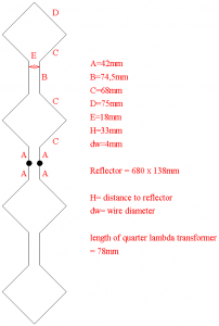
On special request here the dimensions i used for my quados4 antenna. For further information please see the pages of YU1AW.
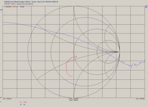
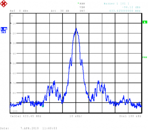
It has to be mentioned that the dimensions appear to be a bit too long which can be seen from the measurement below.
This is although the element was manufactured of 2mm diameter wire.
Datenfunk Treffen 26.06. – Nachlese
Am letzten Samstag fand in Dresden ein Treffen zum Thema Datenfunk im Amateurfunk mit Schwerpunkt Hamnet statt. Ab 9 Uhr gab es Gelegenheit, sich zu Technik zu informieren und rege über Planungen für die nächste Zeit zu diskutieren. Die 16 Teilnehmer kamen aus Sachsen-Anhalt, Sachsen, Brandenburg und Berlin.
Mehr Informationen sind in der Yahoo Gruppe http://groups.yahoo.com/group/digafusax/ zu finden.
Datenfunk Treffen Dresden 26.06.2010
mehr Informationen hier: http://dh5ym.hopto.org/wiki/?page_id=450
Falls jemand den Weg nicht findet, versuche ich auf DB0DD (145.675-) QRV zu sein. Alternativ DB0TUD (438.875-).
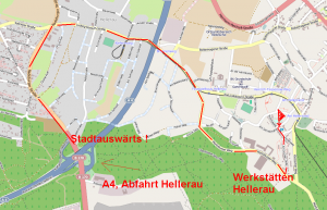
Anfahrtskizze:
Gepante Vorträge:
– Aktueller Stand Hamnet Tests in Sachsen
– Router unter OpenWRT als Gateway zwischen AX25 und TCP/IP (DH5YM)
– Ubiquity Hardware für Hamnet, selber Compilieren und Konfigurieren (DG1CPA)
– Netzkonfiguration im Hamnet (DL1JAD?)
– Aktuelle Entwicklungen bei D-Star
Weiterhin ist es möglich Antennen bis 23cm vor Ort zu vermessen, Hamnet Equipment kann gezeigt und vorgeführt werden. Sicher ist auch eine Vorführung von D-Star mit Siemens C5 und anderen Geräten möglich.
Selbstverständlich ist es auch noch möglich zusätzliche Vorträge einzutackten.
Noch ein Hinweis: Da die Lokalität normalerweise Samstag Vormittag nicht geöffnet ist kann der Wirt bis zum Mittagstisch kein Essen anbieten.
23cm Quados4 antenna
Some time ago YU1AW published some documentation about his experiments and simulations with stacked quad elements for 13cm. He optimized the stacked quad design by changing the distances of the quad elements by using parallel wires in between. He showed that these antennas show some improvements against traditionally stacked bi-quad elements were the distance is too low. He published data for 4 quad element antennas (Quados4), such with 6 quad elements and with 8 elements.
DF9IC published some results with the 8 quad element version recalculated for 23cm. This year DH1FM built two of these Quados 8 antennas for 23cm and used it successfully in contest operation.
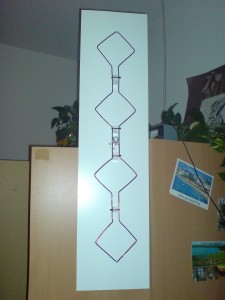
To get a feeling of this antenna type i built the Quados4 antenna for 23cm. A big problem for me was to get it somehow mechanically stable. The accuracy of the quarter lambda transformer and the big distance between the wires at the feedpoint showed some difficulties as well. In the end the antenna seems to work and brings close to 6dB better results than my biquad antenna. But in fact it seems that the distance between the reflector and the antenna element is still too large because it improves if the end elements are bent towards the reflector.
Find some pictures below.
For the future i will try to build a 2x Quados4, means two of the elements above side by side.
DLC7 hardware at DB0TUD digipeater
Since friday/saturday the digipeater DB0TUD operates with a DLC7 (data link controller). This makes the setup even smaller and consumes less power. A further advantage is that the XNET runs native on this hardware which should result in higher datarates although the CPU speed is much less than at the former linux/MIPS solution.
The 76k8 user port and the 19k2 link towards DB0PU use the both modems connected to the internal SCC’s.
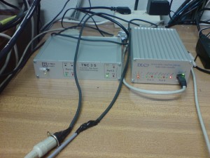
The 9k6 user 70cm, 9k6 user 23cm (currently offline) and 9k6 link DB0DSD are operated with a TNC2 and a TNC3S connected to UART2 of the DLC7. The connection towards mailbox and TCP/IP services goes via ethernet. The serial terminal port remains unconnected for services.
May DUR Activity Contest
This time from JO61XA (Triebenberg) again. The activity was ok but the wheather was poor and stormy during the activity. Only in the end there was some sunshine. This time i did some CW contacts as well. Overall i had 17QSO but quite low average km. Thanks to DL6ABC for the ODX. Until next activity i will try to build a new antenna, hopefully ;)
CAT control of FT-817
Last days i did some experiments controlling the FT817 via CAT. I implemented some basic commands in the math scripting environment Octave (which is a Matlab compatible software). The communication with the serial CAT interface is not possible directly because Octave does not support serial communication. Therefore i used the VSPE (virtual serial port emulator) to connect the serial port to a TCP port which can be addressed out of Octave.
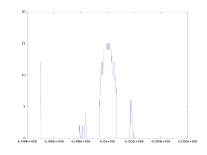
I wrote a script that can tune over a frequency range and reports the signalled S-meter output. In the end a diagramm of the S-meter output versus frequency is drawn. If you have a narrow filter (e.g. 300Hz CW) than you may use this to get somewhat like a “spectrumscope”. Compare the two pictures below which show a D-Star signal in 70cm band recorded with the FT817 and with a R&S FSP spectrum analyser. It is clear that there is a low dynamic range and no information what the S-meter readings correspond to in terms of dB but it comes more or less for free.
Short guide: switch transceiver to desired modulation mode and filter bandwith, edit the frequencies and stepsize in the main scan script, start the VSPE software with correct settings, edit the ft817_connect.m script accordingly, start the scan script.
Find some scripts here: octave_ft817_cat_scripts
VHF Yagi measurements
For our club events we had to reconstruct some old DK7ZB design yagies because too many of the 6mm diameter elements got broken over the years. We decided to modify the design for 8mm elements to get some more material for the screwholes.
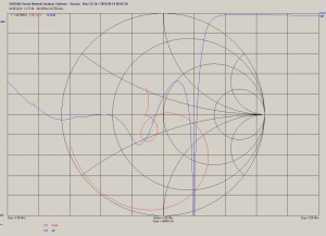
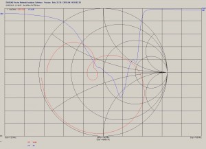
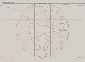
All measurements were done with the VNWA2 with calibration point at the end of a 20m Ecoflex10 cable (directly at dipole connector).
The measurement of the old construction in a high of about 4.5m looked like that:
It can be clearly seen that there is something wrong. Maybe the reason is that some of the elements are going to break and some of them have been already repaired. I do not have a comparison to a version with new elements unfortunately.
After modification to 8mm Elements and optimization of all element lengths with YO with keeping the element locations the picture looks like that:
It can be seen that the best matching of the antenna is slightly too low which is not optimum with some ice on the elements during the march contest. But in general the matching looks like it should now.
For comparison i measured my old 11ele Tonna Yagi as well. The picture surprised me.
The middle of the matching band is around 145MHz which should also do with some minor ice at the elements. The matching itself looks really good. Of course this does not tell anything about how well the antenna works ;)
FT-817 TX spectrum
Some months ago i purchased a defect Yaesu FT-817 radio. It turned out that PA and driver were defect. I was able to buy the PA transistors (RD07MVS1) and driver transistors (RD01MUS1) at DL2JWL (thanks!). I got some really good help in the 817-onair forum.
After the TX was operational i was interested in the output spectrum.
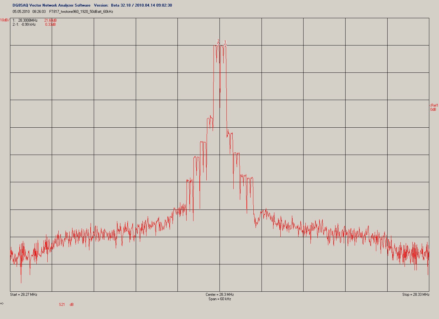
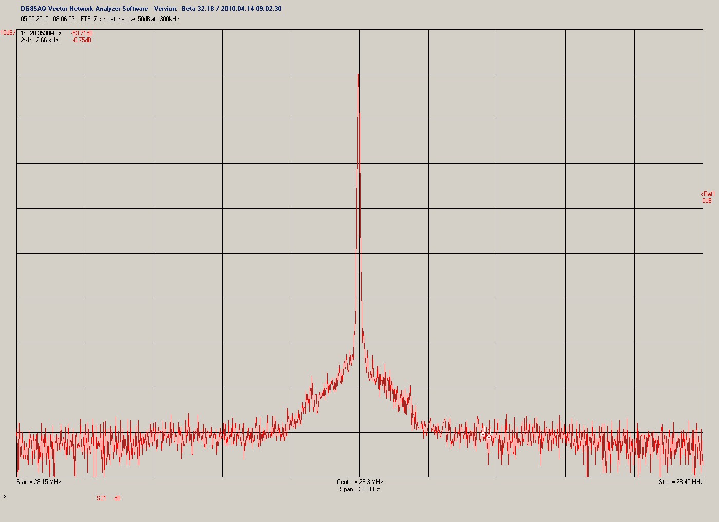
I did a singletone measurement (mode CW, 500mW) and a twotone measurement (mode DIG, 500mW, twotone signal from soundcard). Find the pictures below. The spectrum was measured with the DG8SAQ VNWA in spectrum analyser mode at 28MHz.
Please note that the RBW was 750Hz and you may want to recalculate noise levels.
One word about the twotone spectrum: The VNWA uses rectangular filters. Therefor the discrete tones apear to be rectangular spectrum. The gap inside each of the tones comes from the AC coupling of the measurement system which causes a notch at zero beat frequency.
The measurement results appear to correspond with spectral measurements by some OM in the US done some years before and measurements done by DF9IC. In fact the TX signal is not usable for a real contest because the sideband noise is around -80dBc within a bandwith of 3kHz.
Talk about DG8SAQ VNWA2
Yesterday i held the talk about the VNWA a second time. This time for a local electronics community. Therefore i updated the slides a bit. Please view in fullscreen mode. Here they are. (In german language only !)

