Since quite some while there are 5.7GHz PAs intended for video transmission from drones to ground. Those PA are made with 5GHz WLAN IC and very cheap (below 30Euro including shippment). These PA can be used for 6cm amateur radion but need some modification upfront to generate a usable amplifier.
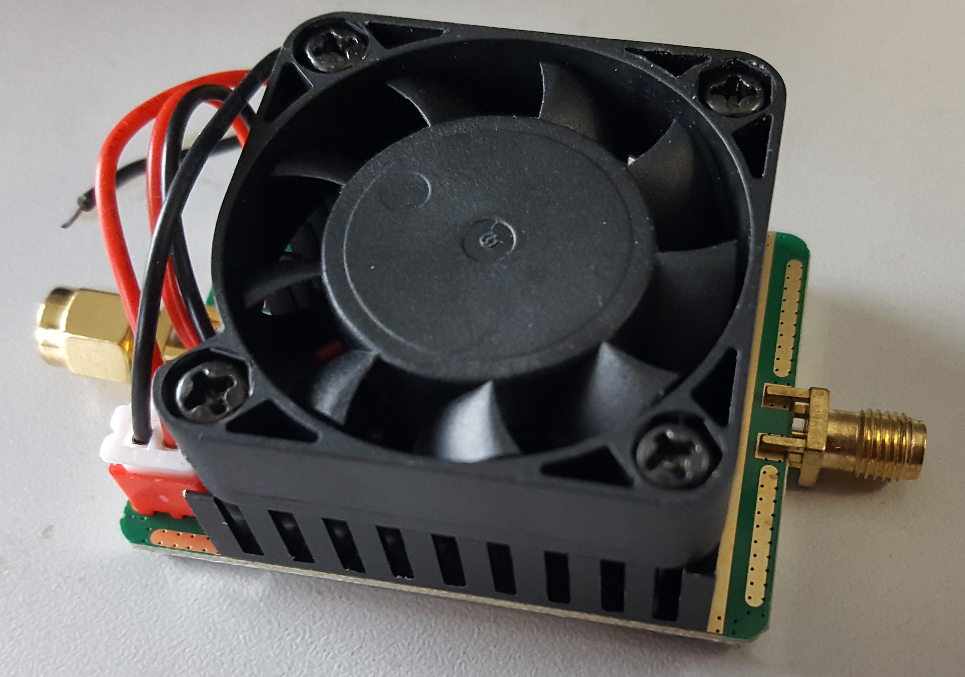
The PA comes with heatsink, small fan and a short power cable.
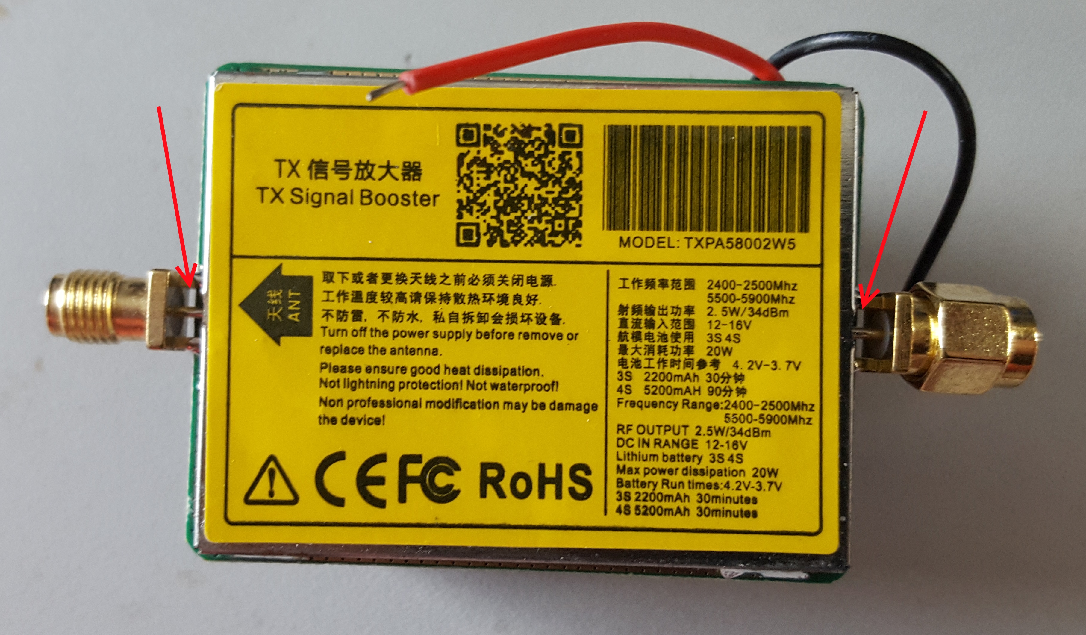
The PCB side has a metal cover that has a sticker with some technical data. The PA is supplied with 12-16V. It is intended for 5.7GHz operation. The sticker also mentions 2.4GHz but the PA will not work there. The specified output power is 2.5..3W although the vendors usually state 5W. You will not reach 5W.
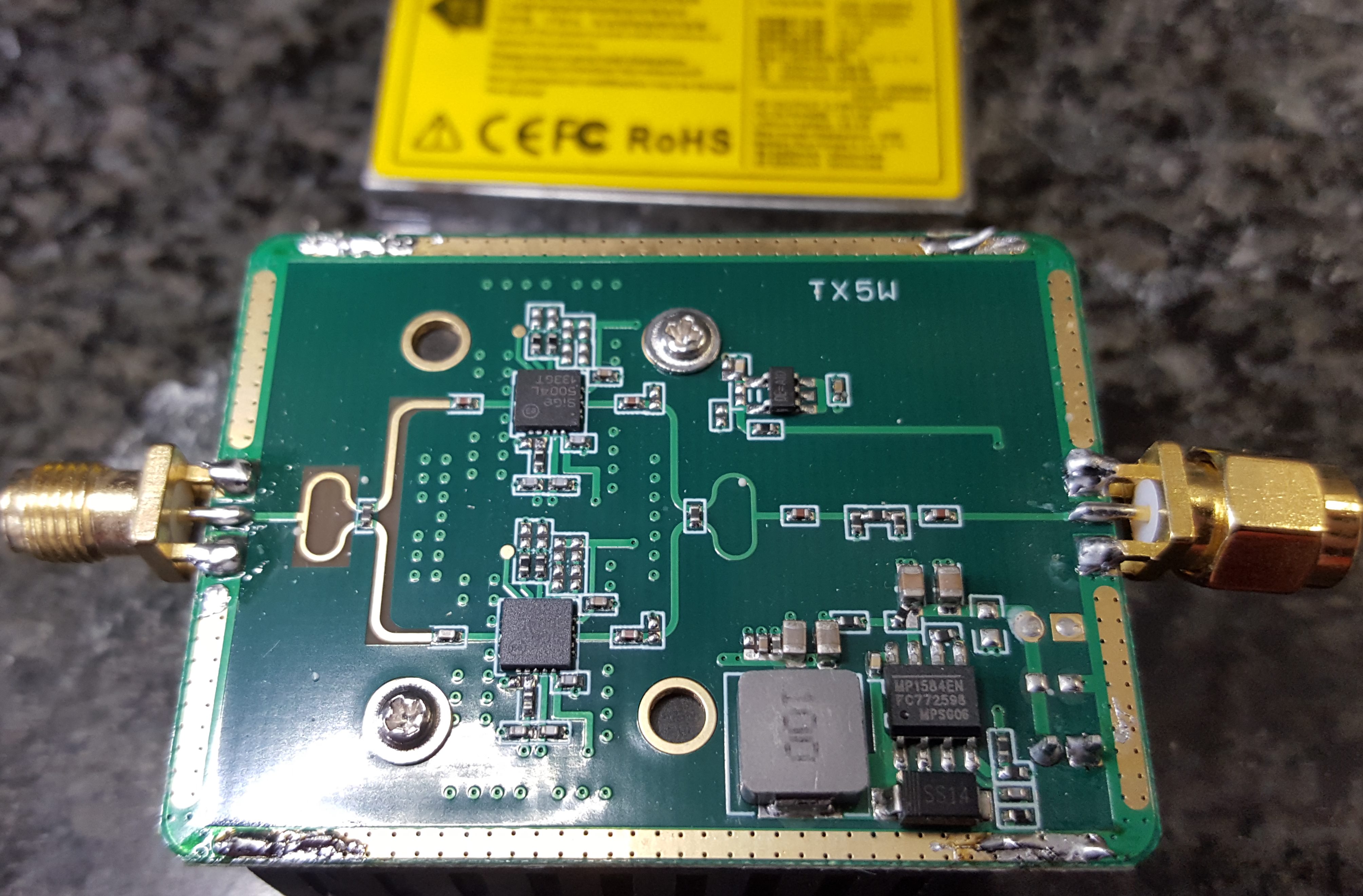
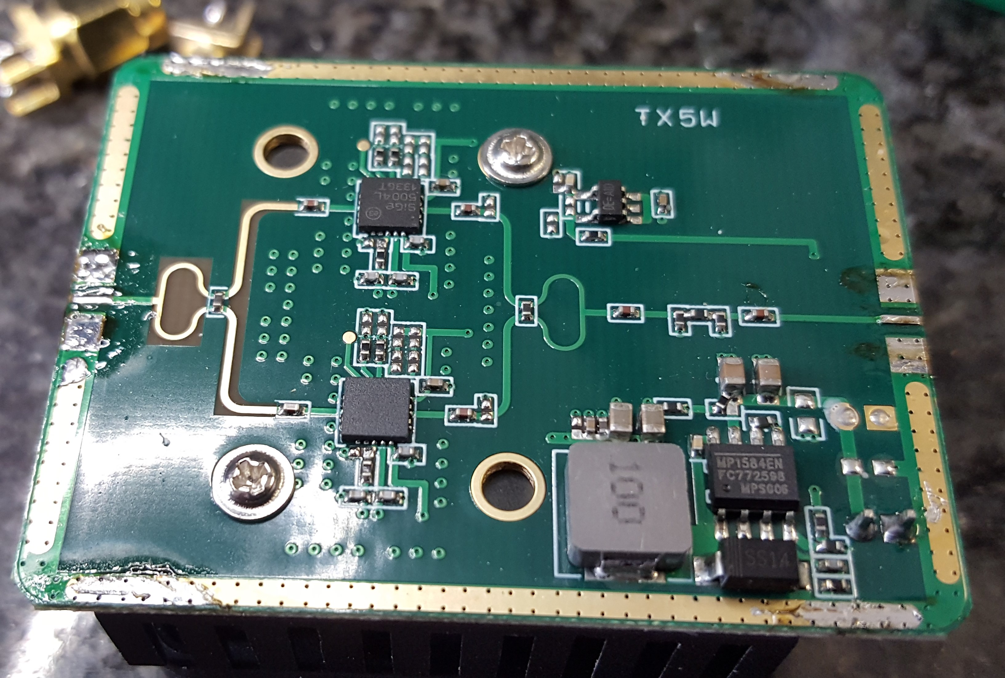
Removing the metal cover shows that the PA PCB contains two Sige 5004L WLAN amplifier IC, some splitter/combiner, an input attenuator and a power supply circuit. The connectors are Reverse SMA (RSMA) and they are mounted really poor. I would not even try to use the PA with those connectors and the air gaps to the PCB.
Now the silly RSMA connectors are removed. The pads need to be cleaned. Also clean the ground ring to prepare re-assembly of the shield later on.
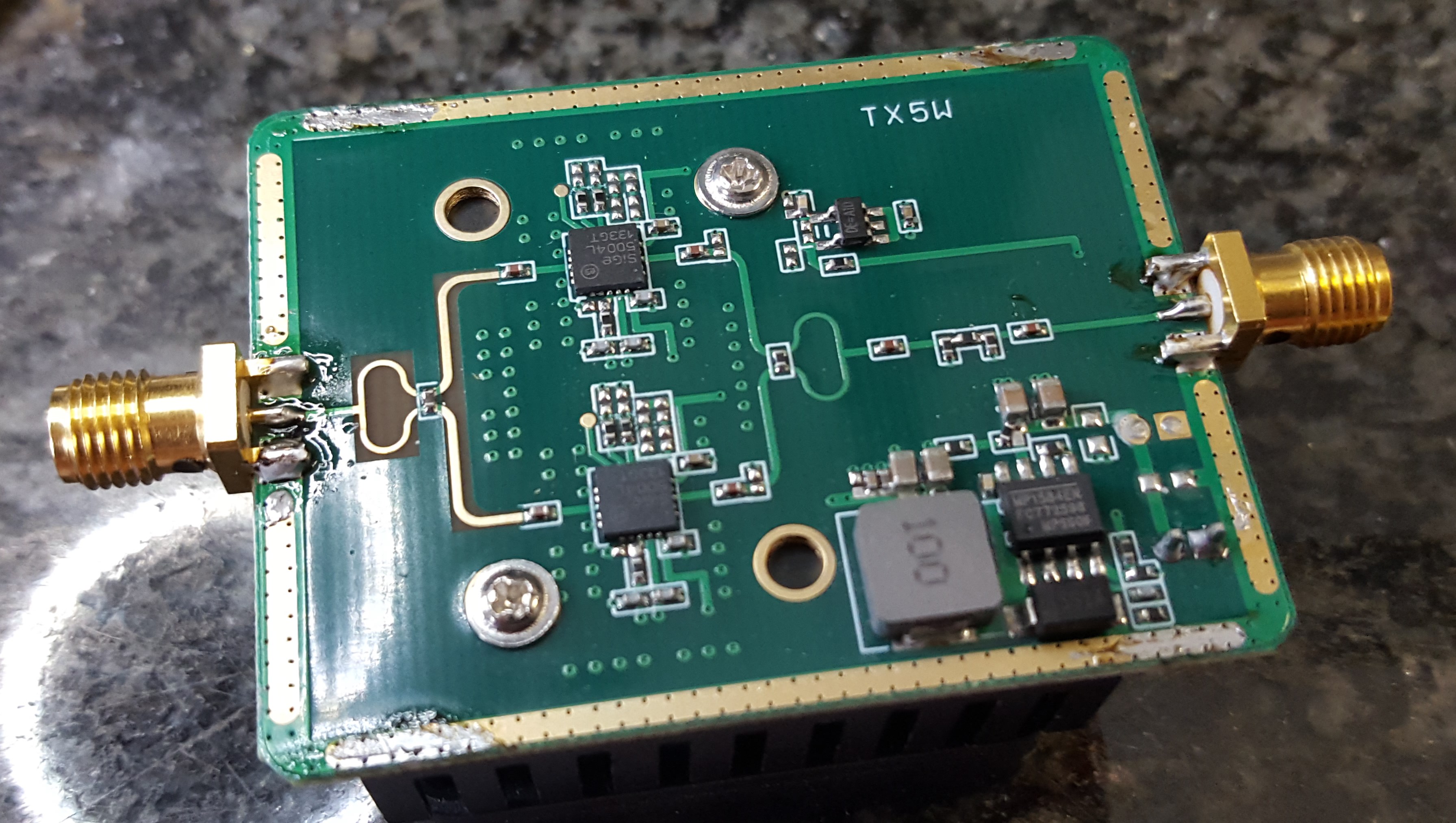
Solder some new SMA connectors. The grounds of the SMA connectors shall touch the top side of the PCB. You need to shorten the ground connectors a little bit. Likely you do not have connectors intended for the PCB thickness. You may solder the other side for mechanical reason. Solder the inner pin of the SMA last in order to prevent breaking the RF trace.
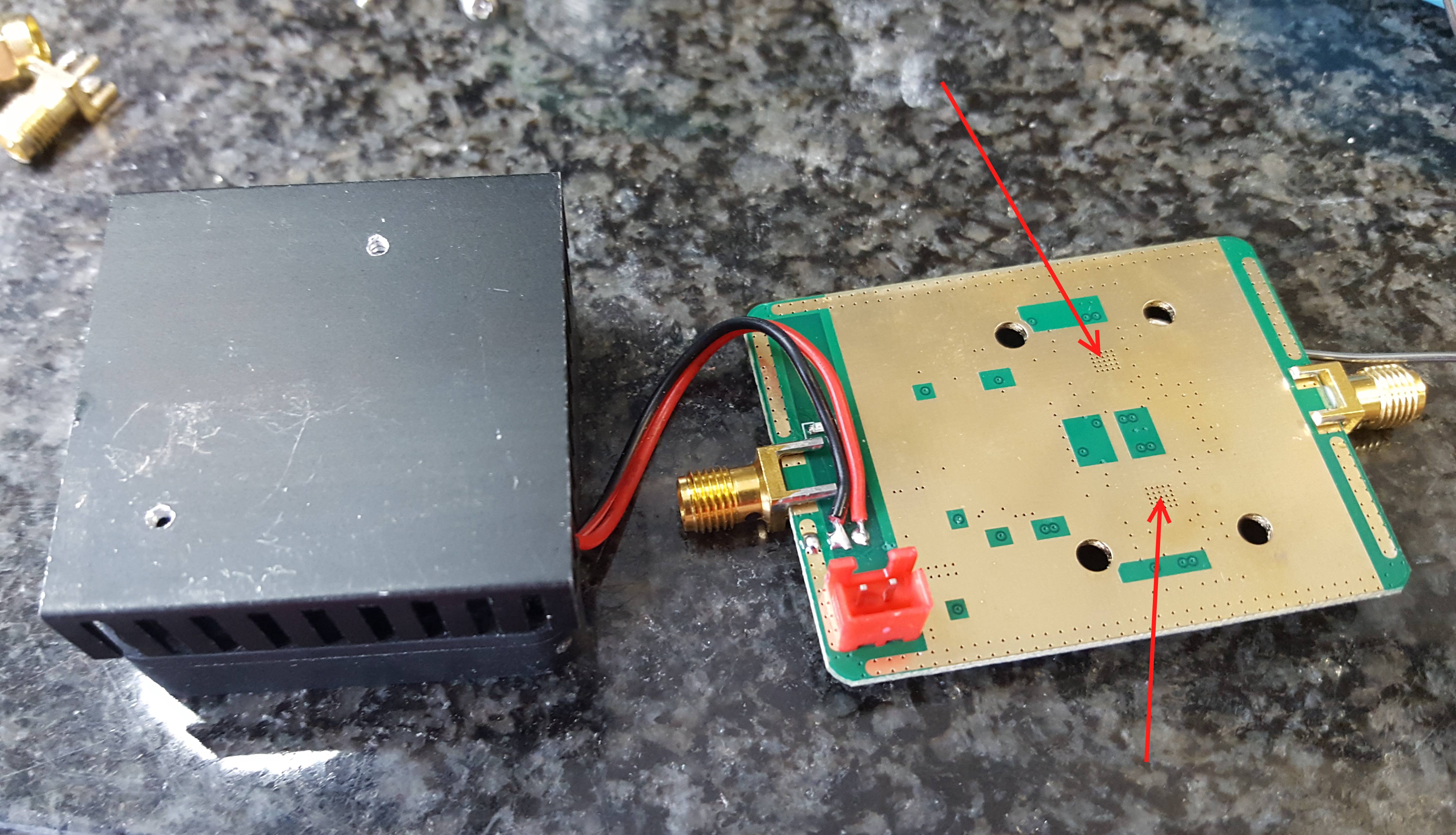
Some attention needs to be put on the thermal conductivity between PCB and heat sink. Removing the PCB from the heat sink shows that cost optimizations safed the thermal compount which makes the heat sink almost useless. So add some thermal paste to the marked areas below the amplifier IC. Probably the switcher IC needs some cooling as well.
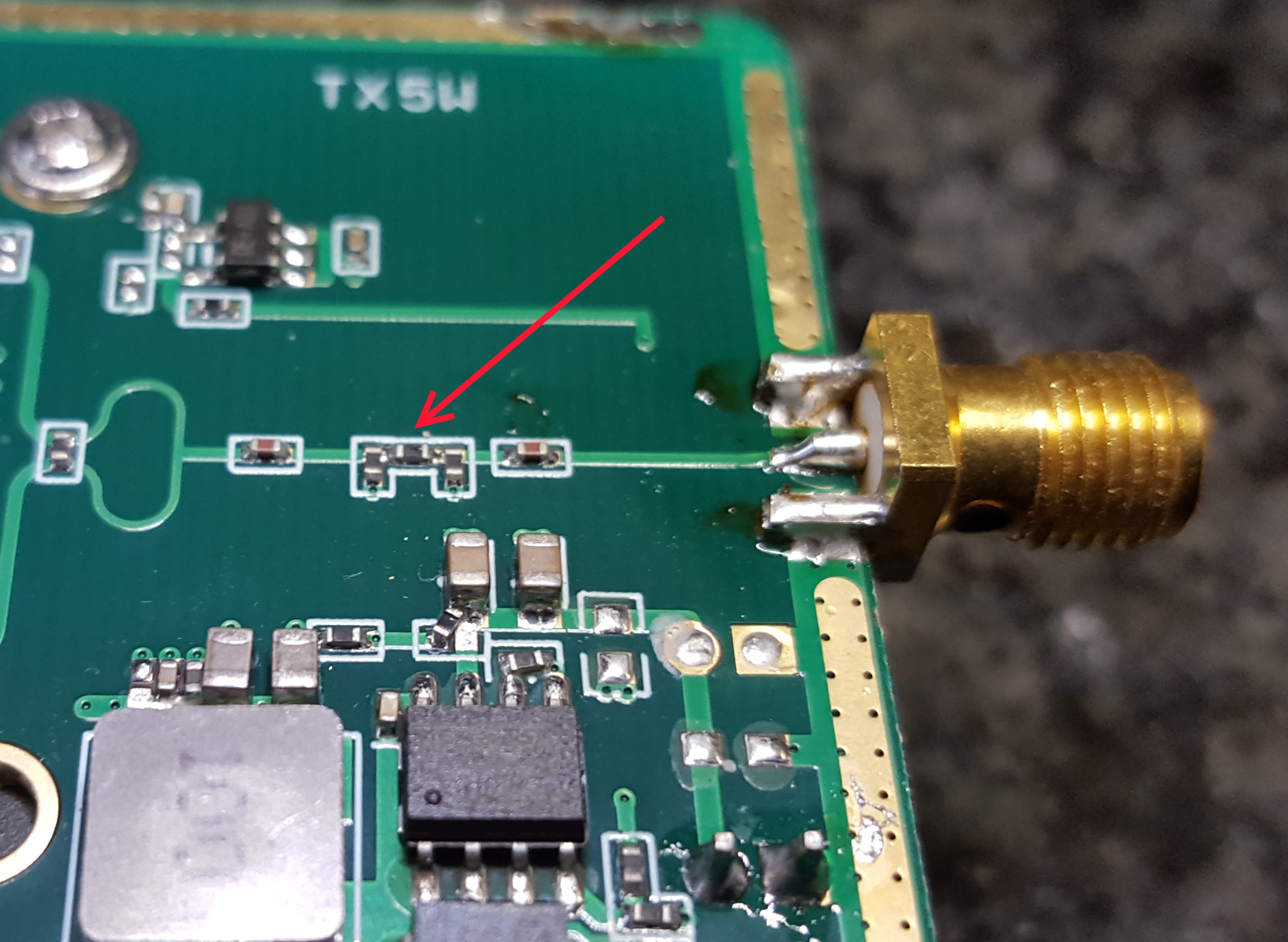
The PA PCB contains a input attenuator. The default attenuation is around 18 to 20dB. If you have less input power you might want to change it. For my measurements i removed the 3 resistors and soldered a 0-Ohm upside down to the middle resistor position. After everything is modified and tested you will likely want to re-assemble the metal shield.
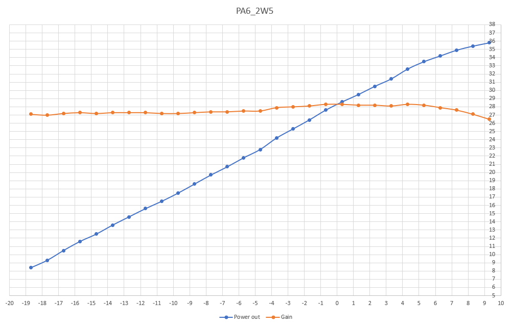
The PA has about 27-28dB gain and my sample achieves 3W output at 7dBm (5mW) input and a current of 1.3A at 12V. Saturation might be somewhere at 4W with 10mW of drive and 1.5A current.