June 16 Microwave contest

Update
My 1st place for 23cm in the german competition survived the logcheck. I am happy with the result although i have to say that there was only one strong competitor DK2MN in the single-Op class. Compared to may the 1st place result is about 12k less. The same points would have been place 9 in the multi-op class this time. Thats quite some difference.
My unplanned 10GHz operation brought position 16 at least.
http://ukw-funksport.darc.de/ukw/result/2016/jun-2016a.txt

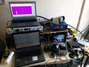
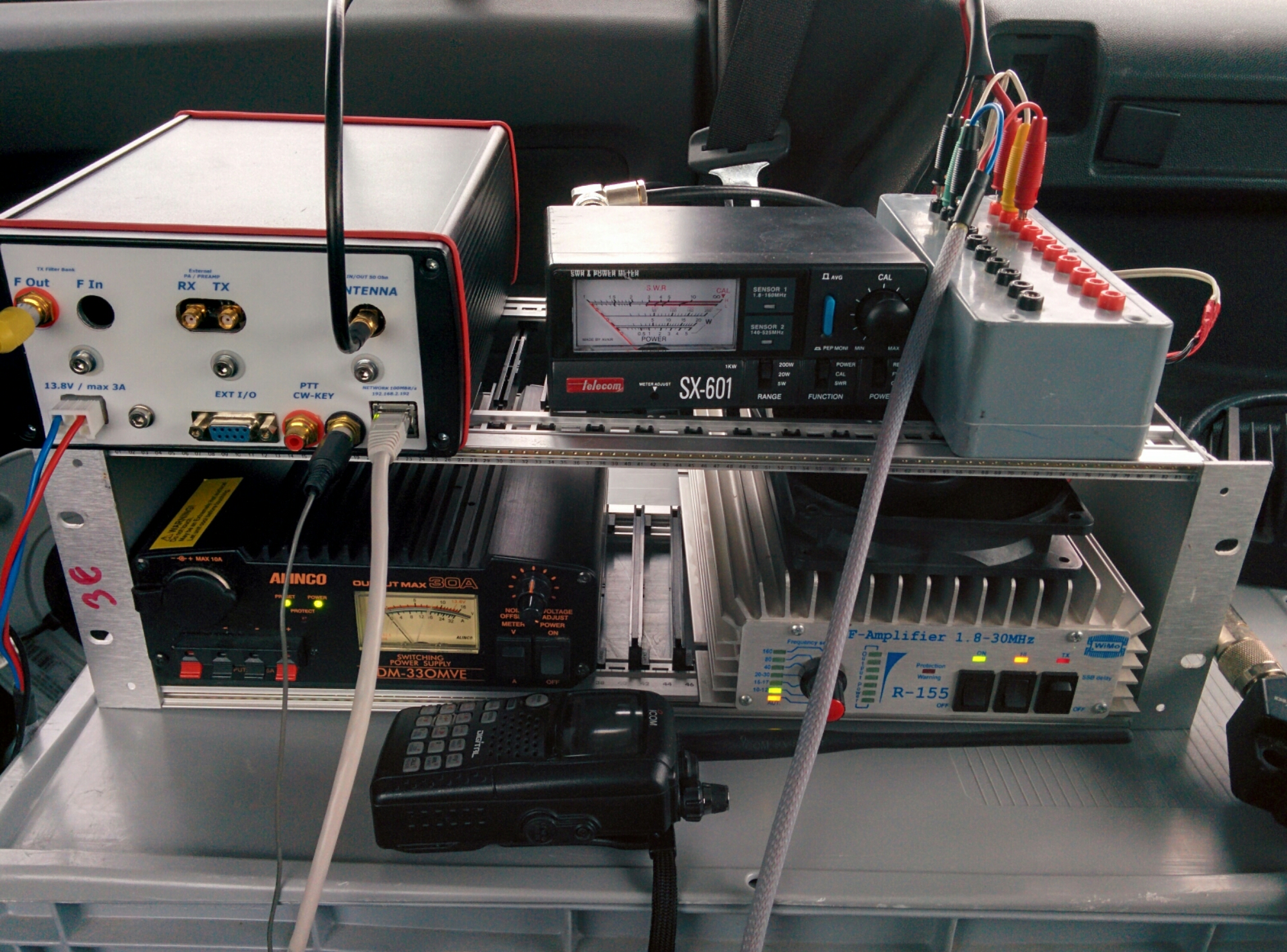
I was operating from JO60OM, Hirtstein. The equipment was as few times before: HiQSDR, DB6NT Transverter, PA 2x100W, 1.5m dish and Quados8 antenna. The thing that worked well for the first time was the control of the antenna from VUSC log via my rotator control unit. Entering the locator, press ctrl-?, here we go.

It seems because of the thunderstorms in many regions over Europe the activity was not very high. Still i made 107 QSO and about 25000 points. ODX was YU1LA  840km via aircraft scatter.

Saturday morning before the contest i decided to take the 10GHz transverter and the 40cm dish with me. That was a good choice actually. Although i just operated that on Sunday and only in north direction i made 19 contacts. ODX was PA0BAT about 500km.

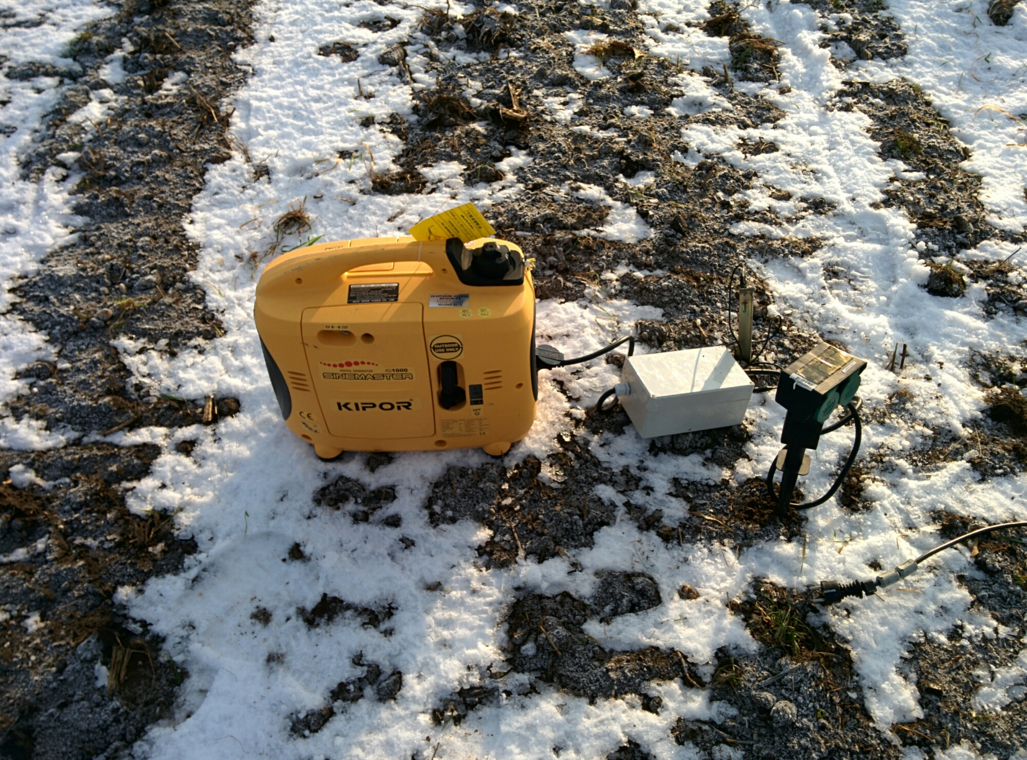
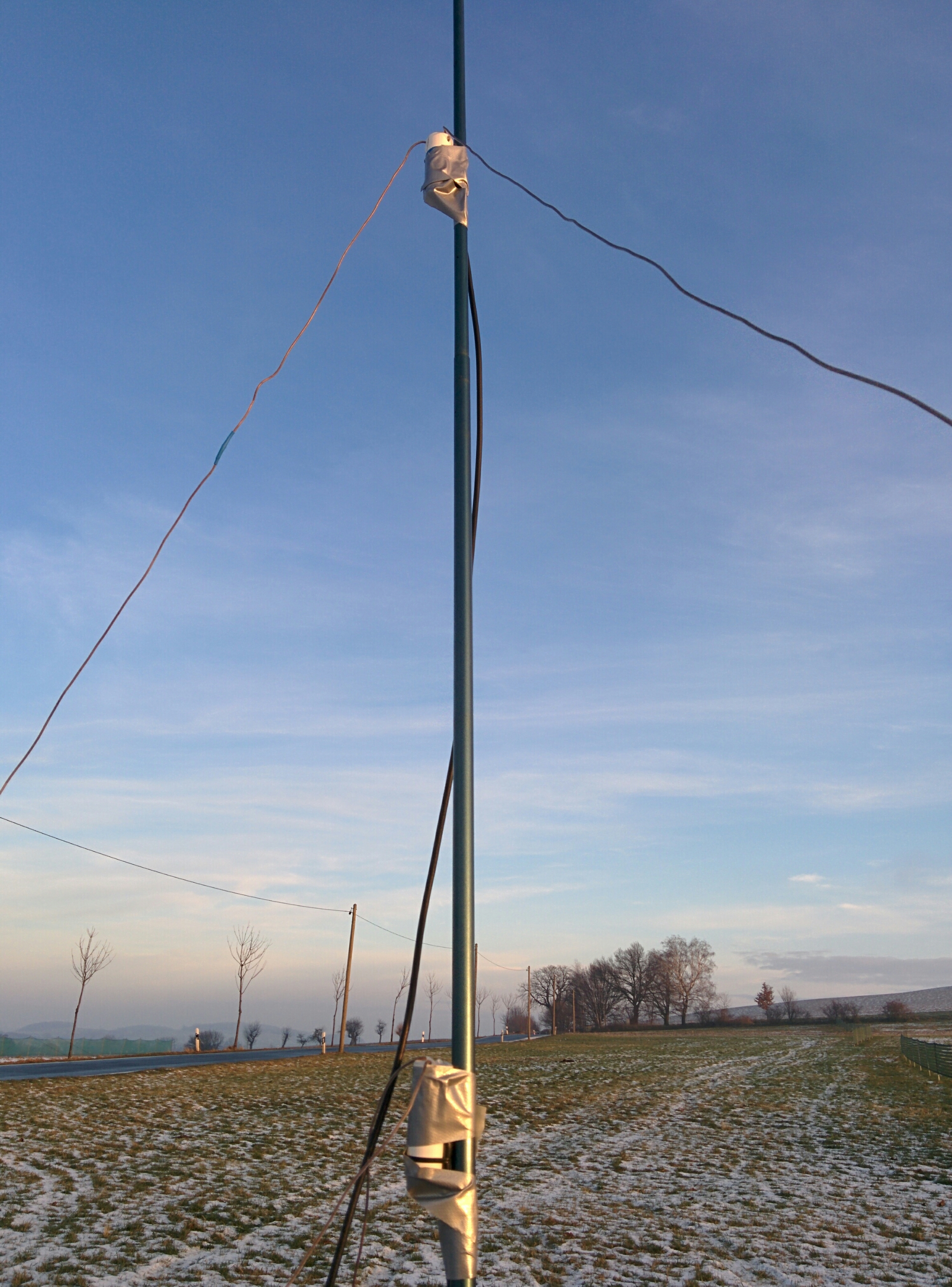
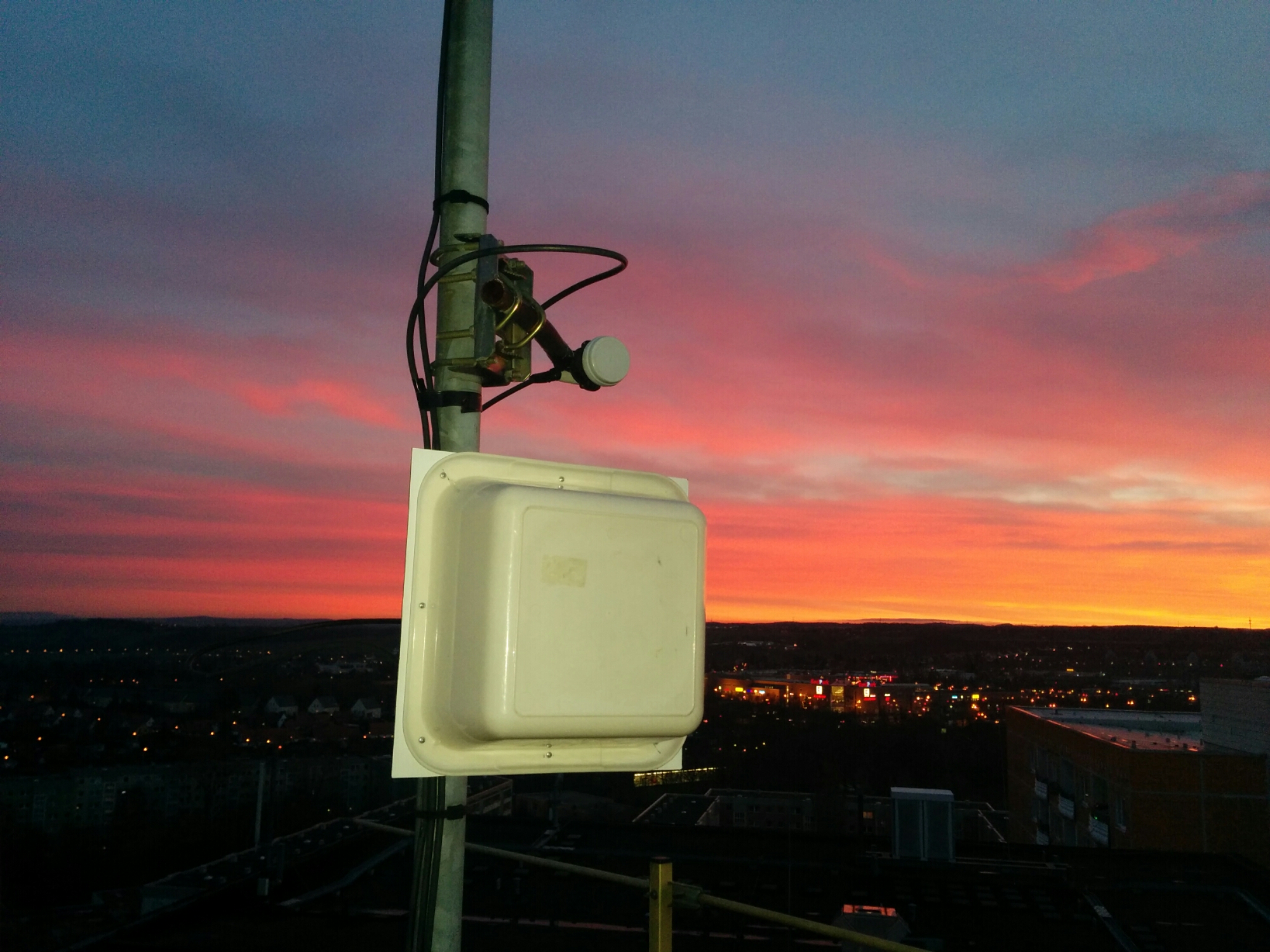
june 2016 rig after the contest

june 2016 rig after the contest

May16 JO60LK

QRV with the DM7A team from Fichtelberg, JO60LK. We worked our various personal calls on 2m, 70cm, 23cm, 10GHz and 24GHz. The weather was sunny but very stormy.
On 2m we tried a tiny 2x2x5ele setup for 2 directions. The gain was somewhat low but still the ODX was about 850km with YU7ACO. We had two newcomer with us who worked on 2m.

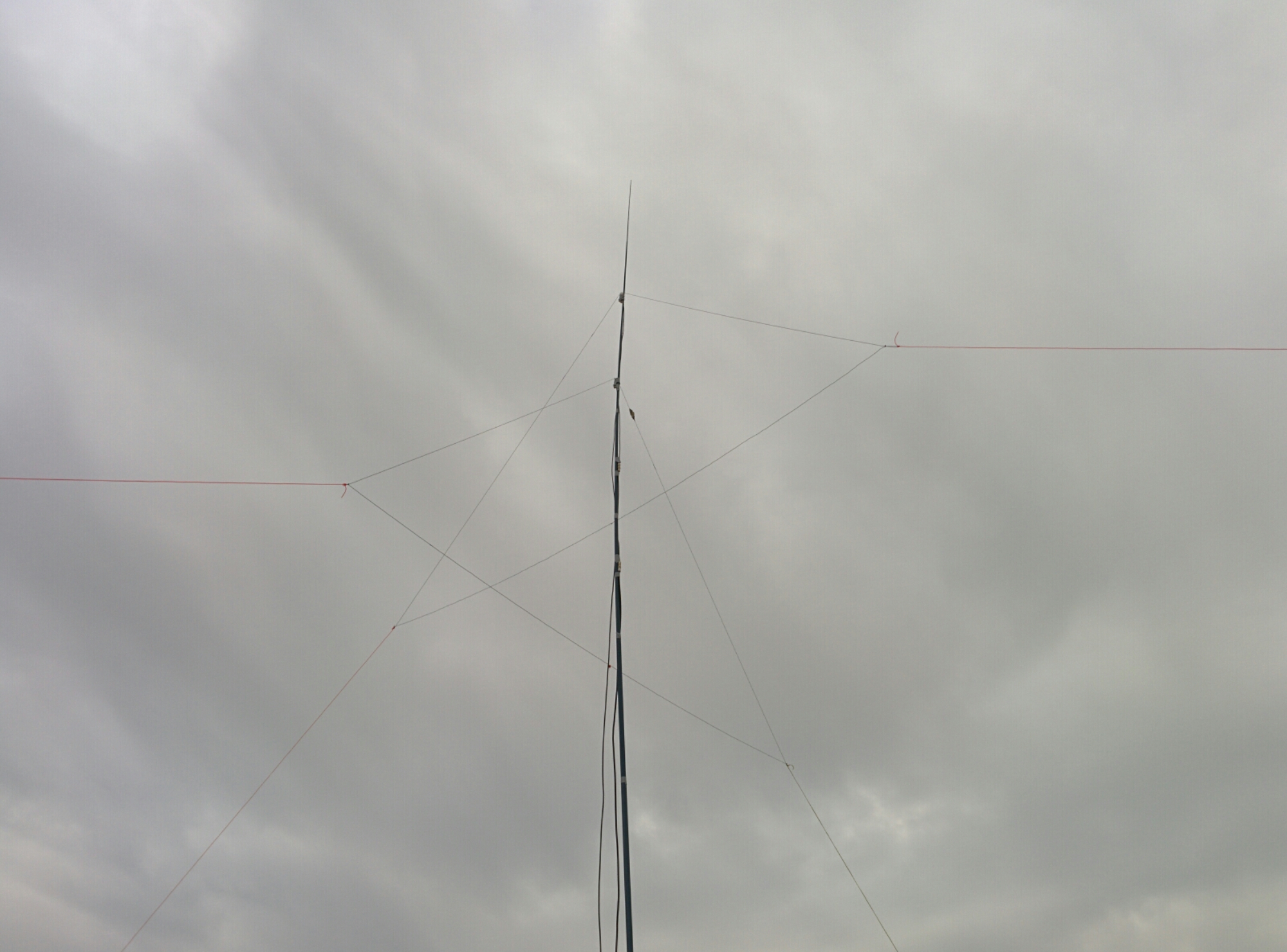
Here an impression of the wind in JO60LK.

V/U/SHF contest May 2016 in JO60LK

and a few pictures:

March 16 V-/U-/SHF contest JO61VB

This time i had to stay home. I used the little time to check the equipment for 2m.
In the end i had 37 QSO in about 3 hours of operation time. Not a lot. Given that i just use a omni antenna i am still fine.

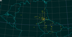
March 16 - stations reached

March 16 – stations reached


I used my HiQSDR + ME2HT setup. This time i used a Odroid board with cwdaemon for keying. With that the rig can be placed anywhere in the house and the SDR/Log PC can be connected via wireless LAN. This enables contest operation from the couch without annoying the family by loud fans or clicking of RX/TX relais.

WSJT-X 1.7.0-devel for Odroid U3

For some tests i finally succeeded to compile WSJT-X 1.7.0-devel with JTSDK.
https://sourceforge.net/projects/jtsdk/files/linux/
The documentation seems to differ from what needs to be done slightly. The difference was that i needed to place the jtsdk-xxx directory in my home directory and rename it to jtsdk. I used jtsdk to generate a .deb package. Find it below. Maybe its useful for someone.
I run a small Odroid U3 board with the Ubuntu 14.04.2 image from hardkernel. The board itself is obsolete meanwhile. Maybe the package can run on other ARM boards too.
wsjtx_1.7.0-devel_armhf.deb
I am not sure what dependencies you need. Please refer to the JTSDK readme if you need some guidance.

This is a screenshot of the software. I did not do a qso yet. So i cannot guarantee that it is really working well.

wsjtx-1.7.0-devel on Odroid U3

wsjtx-1.7.0-devel on Odroid U3

WSPR and 10m Aircraft Scatter

image

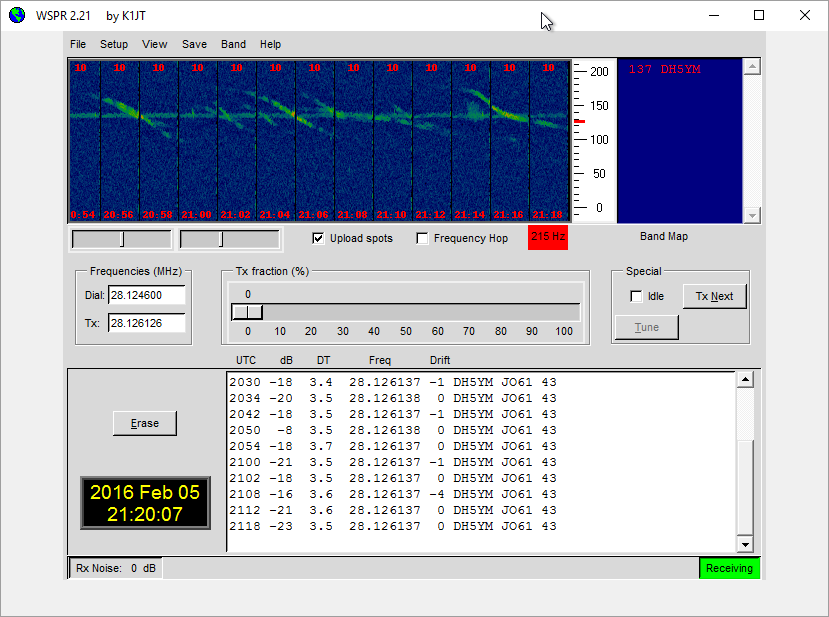
A evening of TX. The picture was made by DK1RS in a distance of 80km and shows my signal (horizontal line) during about half an hour. The crossing lines are reflections from aircraft +- Dopplershift. So far signal raises about 10dB compared to the direct path between Rainer and myself. WSPR cannot decode if the Aircraft Reflection is present because it cannot deal with the Doppler drift.

image

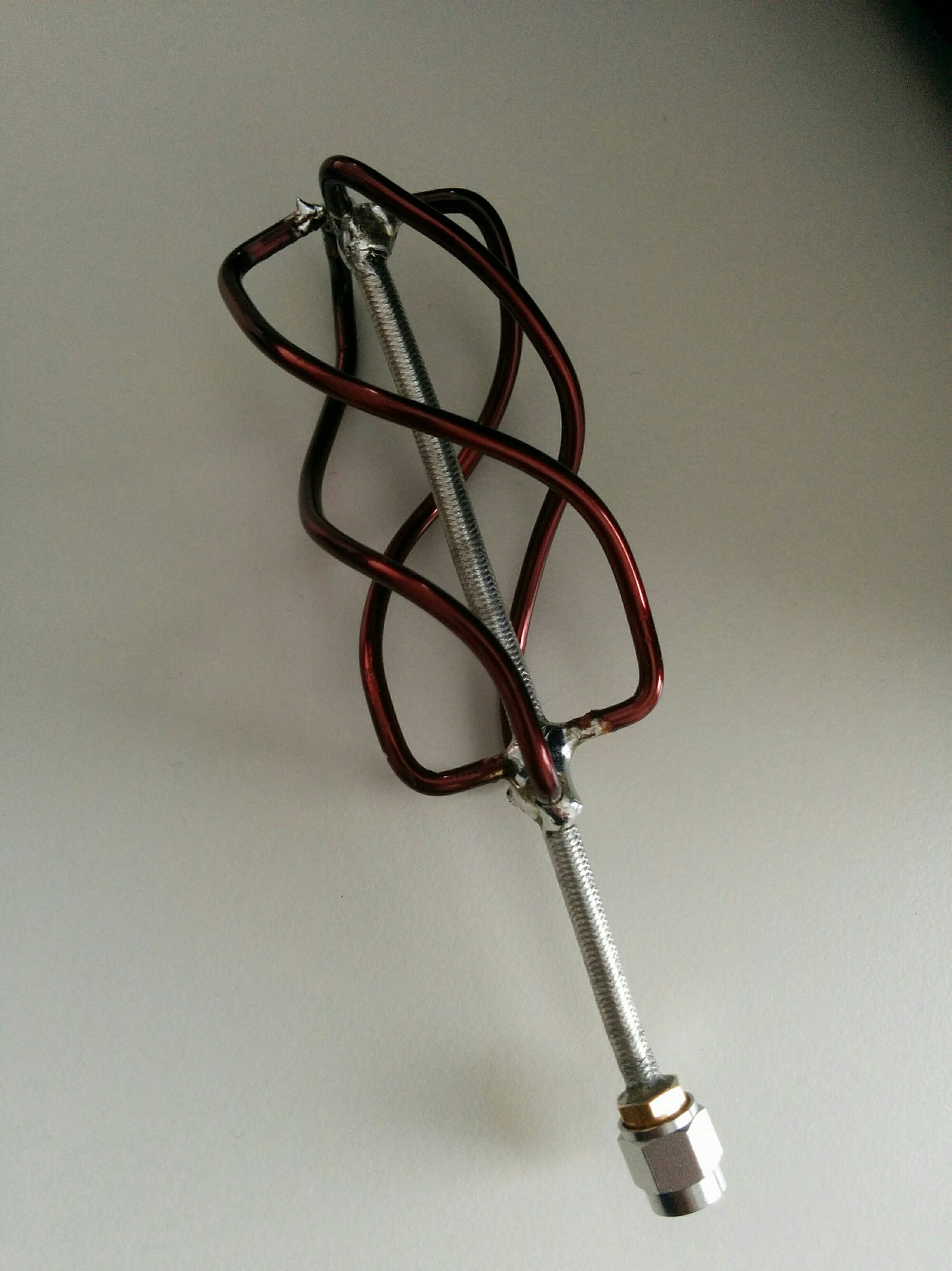
A L-band QFH Antenna

image

A simple project in between. This is a small quadrifilar helix antenna for the L-band. The measurememt does not exactly fit the calculation but for the first trial it seems ok. Probably the thickness of the material was not considered for calculation of the length of the loops.

Attiny2313 based sequence control

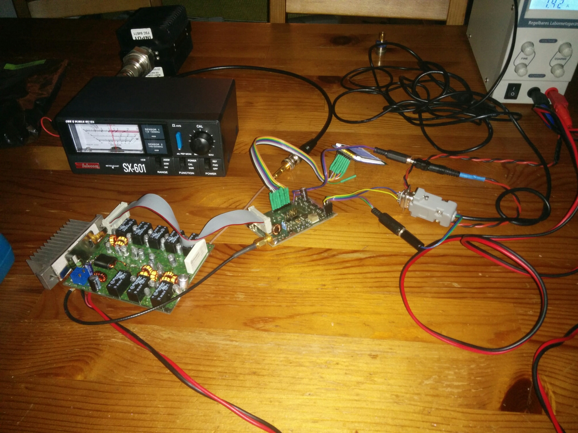
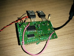
Over a year ago i started building a little sequence control unit for transverter usage. The PCB i showed already here. Unfortunately i made a stupid beginners mistake and used a package that does not belong to the footprint. So the first PCBs can be just brought to life with a bunch of patch wires.

Now i found some time to bring the microcontroller firmware to a usable state and made a short video of operation.

Attiny sequencer

The schematic you can find here:

attiny sequencer schematic

Please notice that the attiny package shown in the schematic belongs to the package without leads which is not the one on the board !

The sequencer has a lowside switch for RXTX relais control and a highside switch for PA supply control as the sequencers from DB6NT have. In addition there is a TX_INHIBIT output that can be used to prevent your Yaesu radio from transmitting until the sequencer has switched to TX entirely. Alternatively you can use it as PTT signal for your transceiver. And there is a kind of “sequencer active” signal that only switches to ground if the sequencer is in TX state (in the schematic its named ERR_OUT but i used it for this function now).

In contrast to other sequencers this one has an error input. If this input is keyed down only the RXTX relais is switched on and the rest of the functionality is locked (means the sequencer cannot switch to TX anymore). It is necessary to release the error input and the PTT to get back to RX state. Together with the “active” output this can be used to lock several transverters against each other for example if they are used with a common dish.

In addition i equipped the board with a ULN2003 darlington array that can be used as 7 port lowside switch to realize further switching outputs.

As i told before a somehow messed up the layout. Thats why i do not publish it here. If there is some interest i can update it to the correct package and make it available. However i show some more pictures of the prototype unit.

top side - LED at the PA output, lamp at the relais output

top side – LED at the PA output, lamp at the relais output

bottom side - attiny2313, uln2003, few transistors, diodes, ...

bottom side – attiny2313, uln2003, few transistors, diodes, …

In the second pictures you see the necessary patchwires. Fortunately GPIO are software configurable ;)

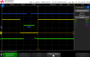
Switching behavior is normal for a sequencer. The yellow line is PA relais output, the green line is the PA supply voltage, the blue line is the TX_INHIBIT output. The PTT input signal is not shown here but was asserted from start of relais until the TX_INHIBIT signal goes high again.

sequencer switching

sequencer switching

Further ideas for the circuit are welcome. Some i already got. E.g. controlling rotary RF switches. I will look into that.

MMC2015@JO60TR

Last weekend i was able to participate in the Marconi Memorial VHF Contest. First of all many thanks to DL4DTU and DL3DTS for giving the possibility to use their great QTH in JO60TR together with the antenna group 4x9ele + the amplifier !

I used my HiQSDR already few contests before. Now i wanted to try on 2m as well. I decided to purchase a ME2HT-Pro transverter which perfectly fits the transverter input/output of the transverter. You can see the setup on the picture below.
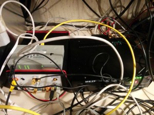
HiQSDR + ME2HT-Pro

HiQSDR + ME2HT-Pro

The SDR is controlled from the Quisk software. I usually use 196kHz bandwidth setting. This time i tried the CWSkimmer software. Quisk can forward the received baseband samples to a audio loopback device which is fed into the skimmer running under Wine.

The first time i used the very powerful Tucnak log from OK1ZIA. The log got the skimmer spots. In addition also Quisk connects to the skimmer. If the center frequency shifts Quisk tells the skimmer the new center frequency. This is required to always get correct spots. From the bandmap and the cluster window of Tucnak its directly possible to control Quisk like a hardware transceiver. In addition Quisk has a 2nd RX that can be used  to listen to other frequencies in between the CQ loops. The picture shows the SDR PC on the right side and log PC on the left side. On request of some OM i also fed the skimmer spots into the reversebeacon network. Sometimes i had the impression that this caused sometimes other stations beeing faster than me ;)
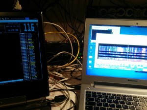
Log and SDR PC in JO60TR

Log and SDR PC in JO60TR

The big advantage of the skimmer connected to the local system was that i immediately noticed when DX stations were heading their antennas in my direction. Looking through the skimmer spots i noticed that i still missed quite some station from DX.

To avoid turning the antenna array all the time i decided to use a second antenna system. In addition to the 4x9ele of Norbert i mounted my DK7ZB-Oblong to one of the other masts at the QTH. The array ran with about 400wtts and the omni antenna with about 200wtts. Reception was selectable from either the one or the other antenna.

Overall the setup was working quite well. The only part that really caused a lot of trouble was the sequencer required to switch the various relais in the correct order. The microcontroller in the setup had problems to keep the PTT. Impulses from the switching relais caused the PTT input of the sequencer to raise for a short moment and afterwards the PTT was not detected anymore. Sporadically my transmissions got interrupted by that effect. Sorry for that. In addition i had some minor trouble configuring all the software correctly since the IP network setup was quite different than at home. I also had to extend my wireless internet access 2 times. One time because the Windows VM with the aggregator software wanted to download a Windows10 update ;)

In the next picture you see the map of the worked stations. The result was about 250QSO and a bit over 80000 points raw score with a average of about 300km per QSO.
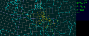
QSO map mmc2015 from JO60TR

QSO map mmc2015 from JO60TR

Last but not least i want to show some spectrum screenshots from the contest.

The Erzgebirge is known to have a high density of VHF contest stations from OK and DL. Therefore the band is very full.
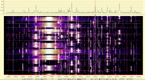
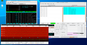
waterfall mmc15

waterfall mmc15

Within the waterfall history its a lot easier to find a free frequency than with a normal transceiver. You also see in which direction you need to move if one of the other close high power stations comes too close. For the close high power stations you can also see the problems of the different transmitters that can cause wideband interference.

Example 1: Phasenoise of the transmitter
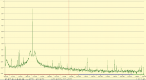
poor TX phasenoise

poor TX phasenoise

This is really a poor example since the noise is less than 70dB below the carrier.

Example 2: Keying clicks causing splatters
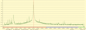
keying clicks

keying clicks

In that example the spectrum of the oscillator is a lot better. But the hard keying of the TX causes leakage to other frequencies about 85dB below the carrier. The level was rather low but remember the proximity and the high antenna gain and TX power.

I wonder if someone can give me honest feedback about my own TX signal…?

73 de Mario, DH5YM