The picture shows a pipe cap filter experiment for 6cm. The 3/4″ pipe cap filter can be tuned between about 3.4GHz and 13GHz (see below).

Pipe cap filter for 3.4 to 6GHz range
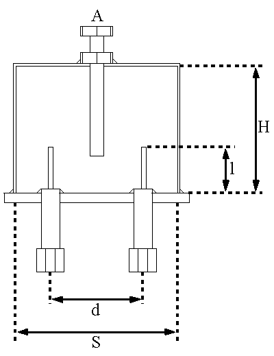
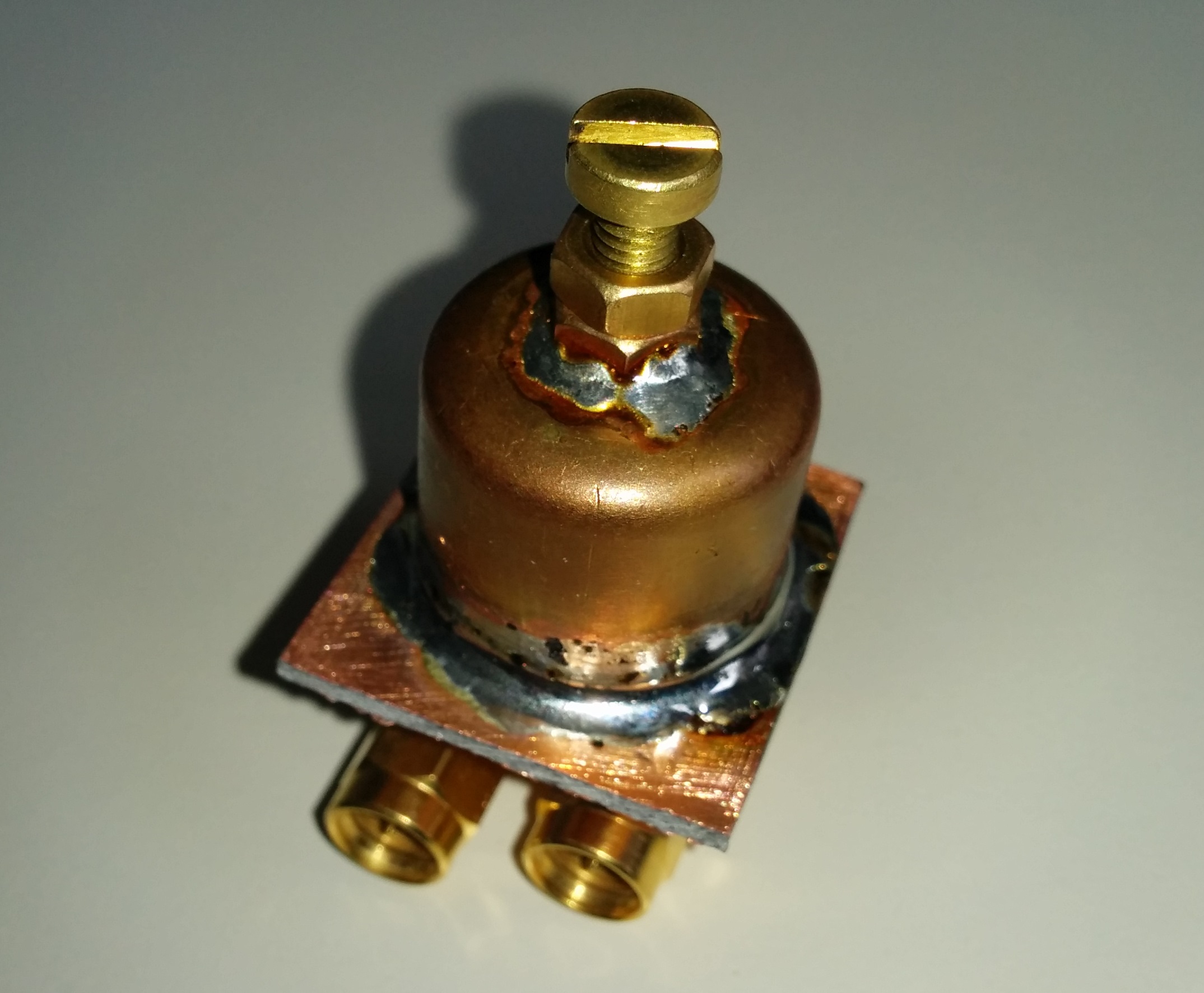
The filter shown here approximately looks like that (screw is M4, 4mm diameter type):
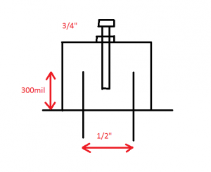
pipecap filter example for 6cm
Some nice paper about constructions of pipe cap filters can be found at W1GHZ.
http://www.w1ghz.org/filter/Pipe-cap_Filters_Revisited.pdf
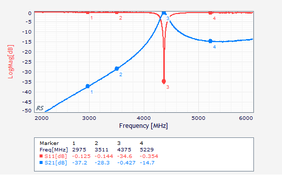
The measurements show about 0.4dB insertion loss. Do not expect to much suppression. As a simple RX image reject filter or for multipliers its certainly a good option.
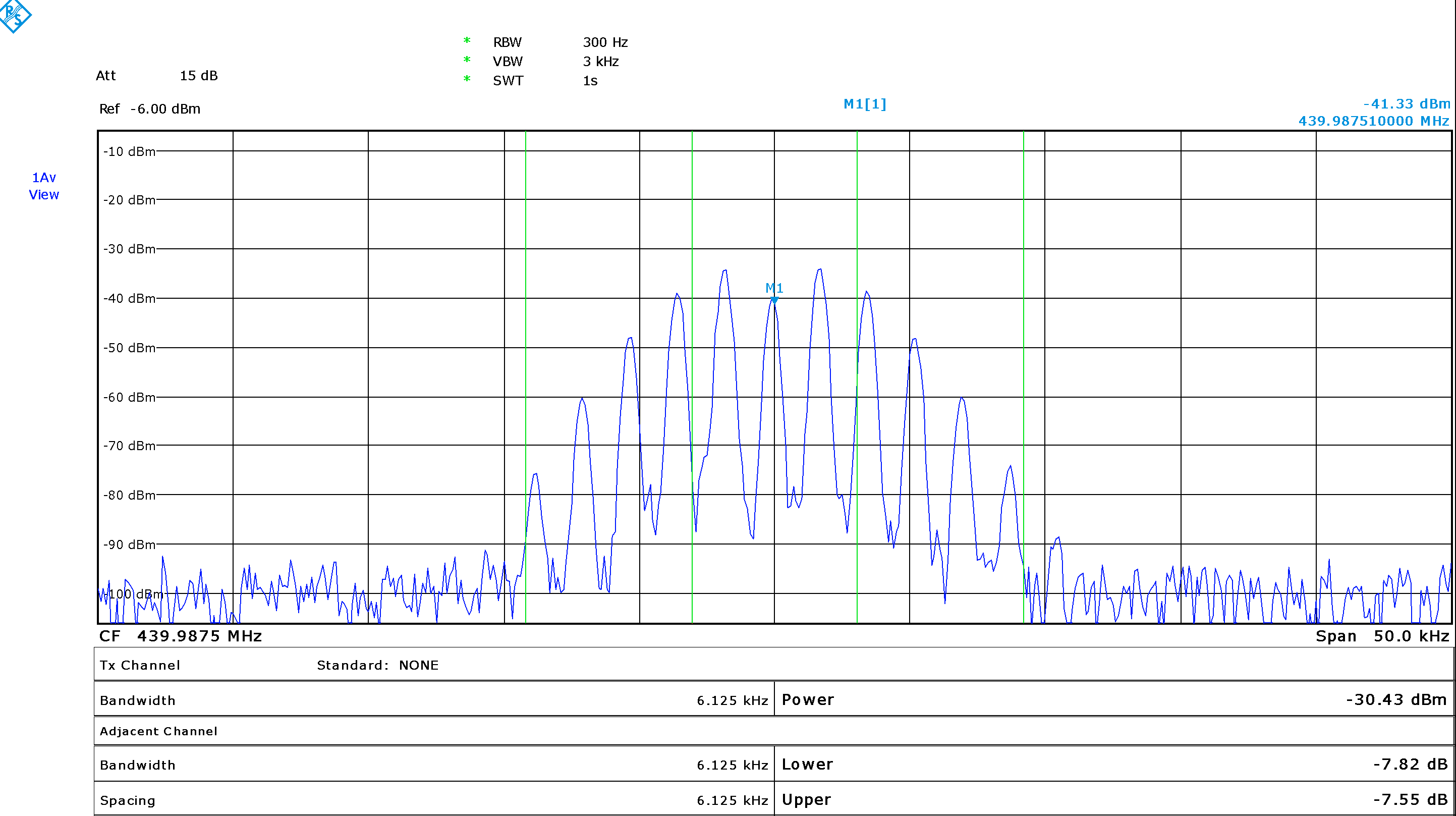
S-Parameter for filter tuned to 5720MHz
However for my construction it seems that the rejection above the tuned frequency is not very good. According to the paper of Paul it seems i have choosen for too long probes.

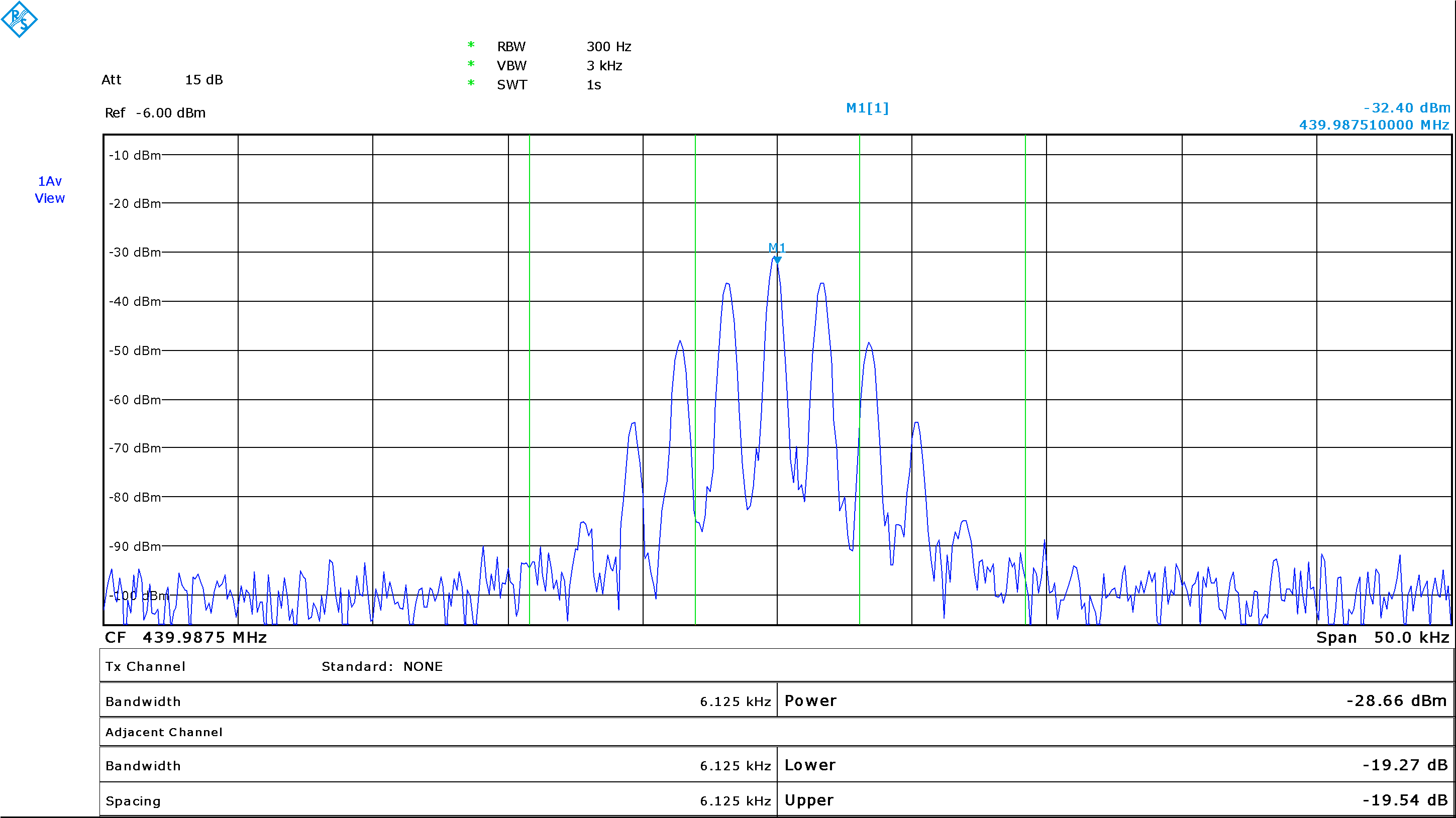
S-Parameter for filter tuned to 4375MHz
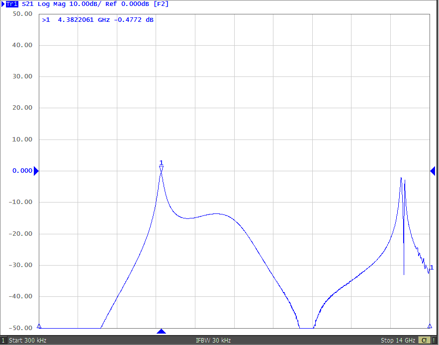
[Update1 – wideband measurement]
DL2MRE provided some extended measurement of the filter up to 14GHz.
I have to say, that it looks better than i thought. I was expecting worse suppression at high frequencies due to radiation but it is ok. The resonance at about 13GHz might come from the 90degree SMA connectors. However the bandwith is rather large and has an unexpected shape. Might be some parasitic effect ? Thanks to Marcel !
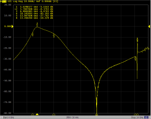
pipe cap 6cm wide measurement 4-14GHz
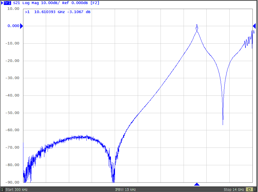
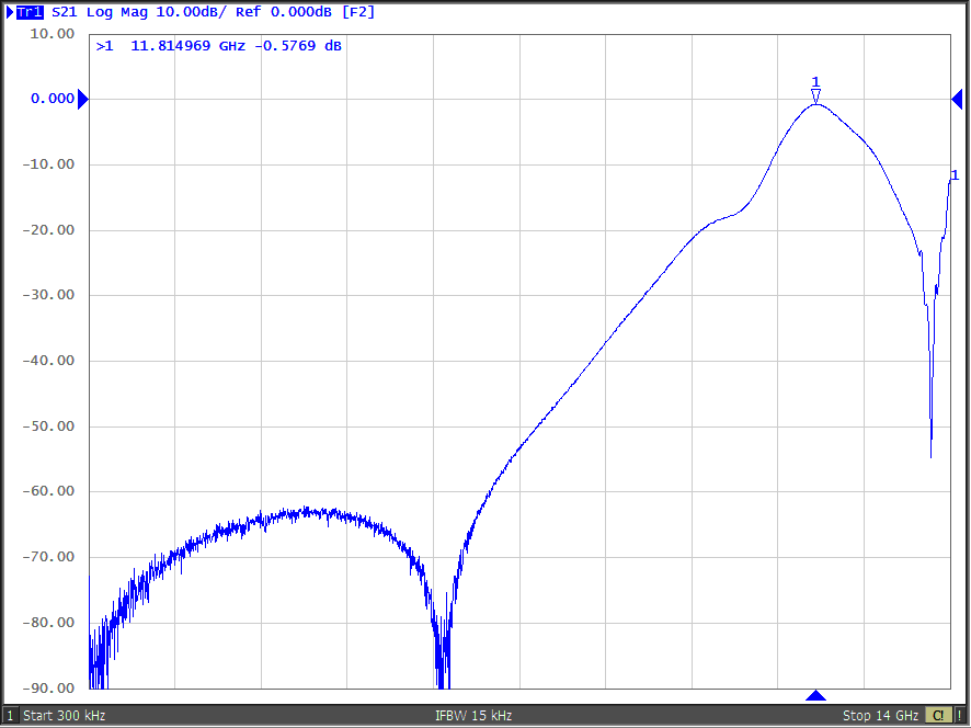
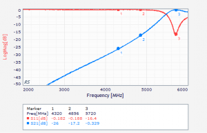
[Update2 – unwanted response and tuning range]
Marcel made some more pictures with the filter tuned to different frequencies.
It can be seen that there is some unwanted respone of -15dB around 7GHz. This stays more or less static with respect to the frequency the filter is tuned to.
From above you see that the coupling probes have 11mm length. 11mm x 4 in wavelength equals about 6.8GHz in free space. So direct coupling between the probes is the most probable reason.

Filter tuned to 4380MHz
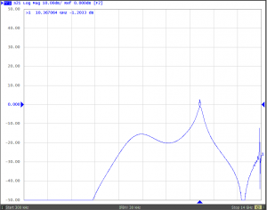
Filter tuned to 10368MHz
Another outcome was that the tuning range of the filter is very large from about 3.4GHz up to 12 or 13GHz.
Because of the static unwanted filter response i decided to open the cap again and shorten the probes to about 5mm (so about 15GHz). As described at W1GHz this has significant impact to bandwith and insertion loss of the filter. Now it is rather hard to tune it to the correct frequency. I will post some measurement results later.