Our local club DARC chapter S07 participates in the DARC Club competition. See our results page here (external).
Because of the UHF/SHF contest and the CW Fieldday both contributing to the Club competition we went to our portable QTH in JO60OM. There is a great mix of high altitude and very nice accomodation. Find some report of DL6JZ here.
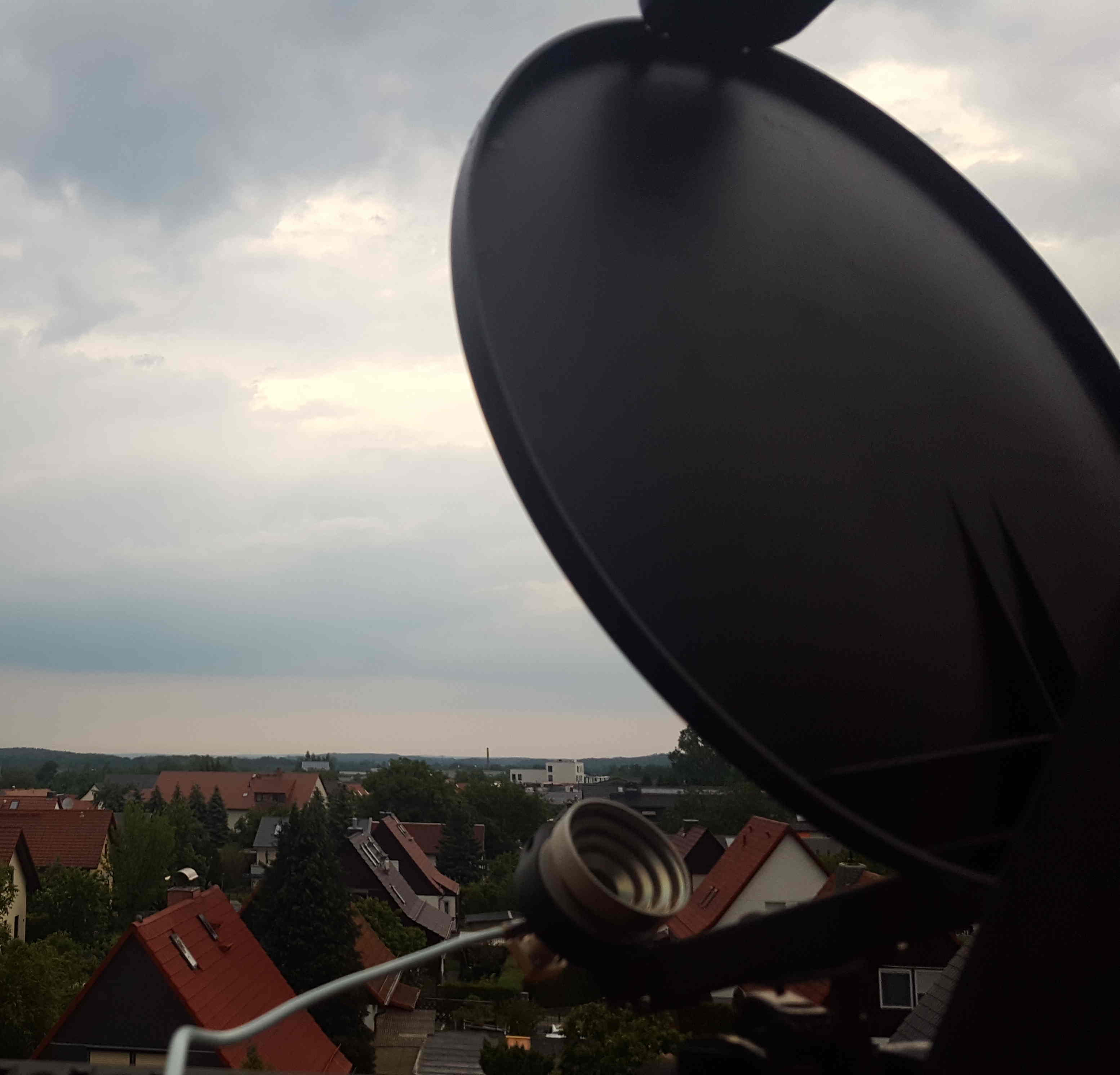
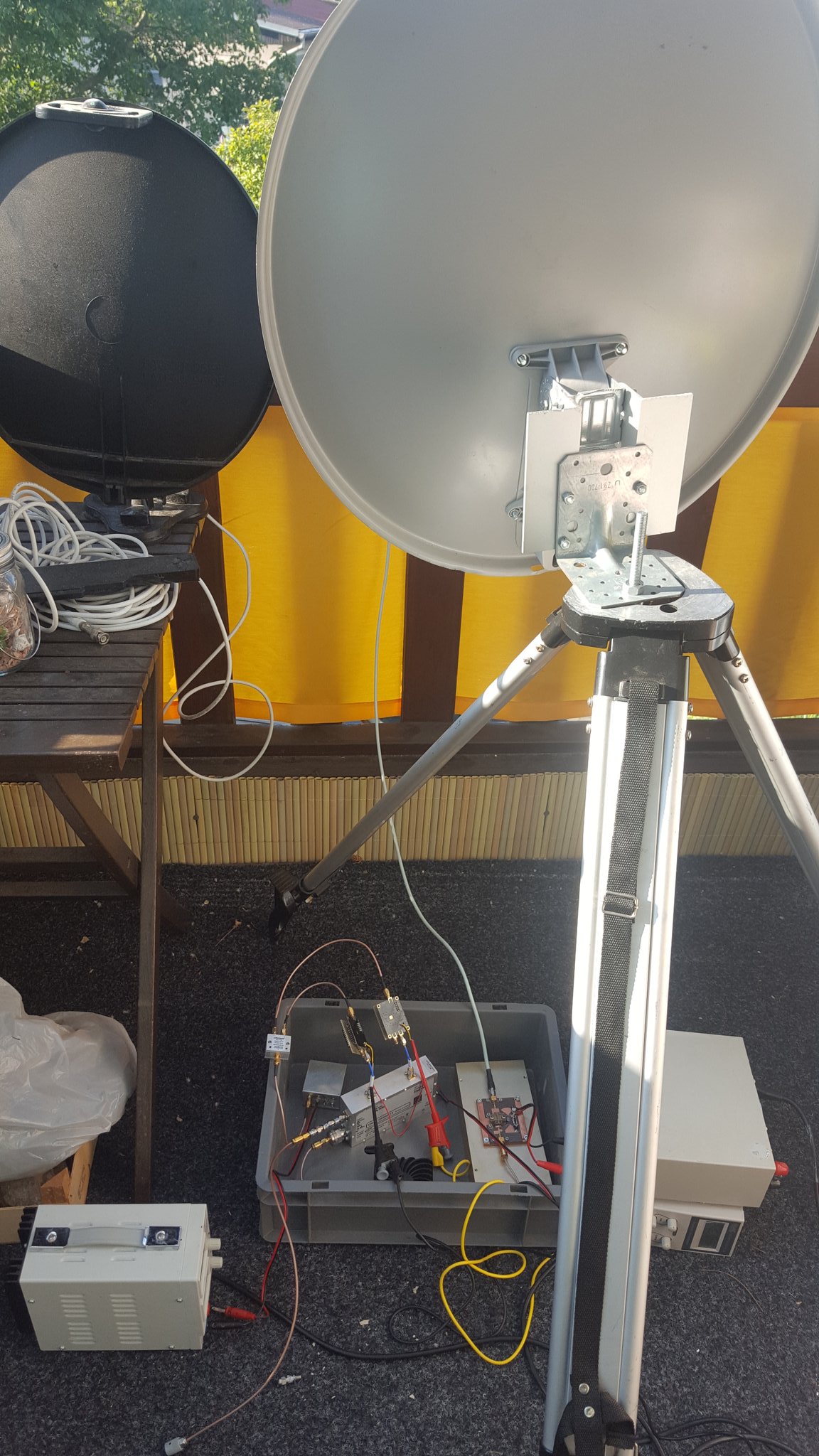
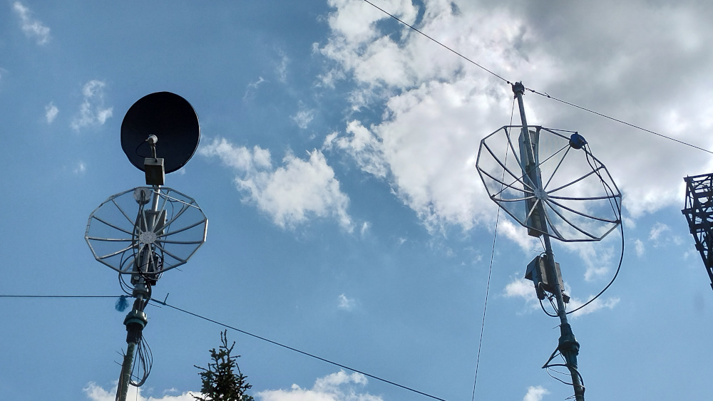
Because of some family struggle i went to my parents home already friday evening. From there its only a half hour trip to Hirtstein. We met in JO60OM around noon and started to put the equipment. This time i took my 1.5m dish for 23cm and the 1m dish was planned for 13cm. Fred also brought his 6cm and 3cm systems.
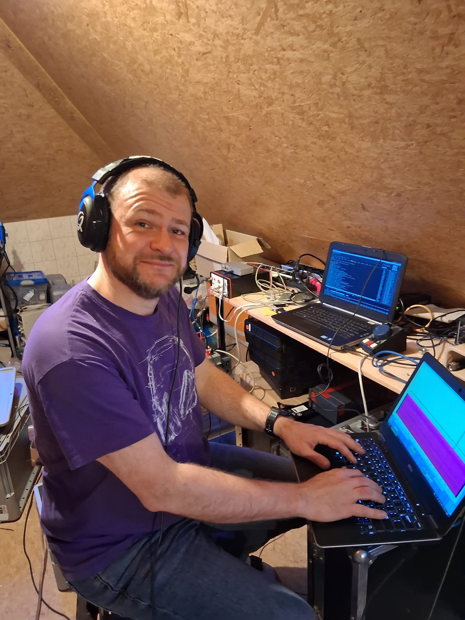
The 23cm was my favourite configuration with 2x 100W (one for front system and one for the backside), the 23cm transverter with 10m IF and my HiQSDR. The Quisk SDR waterfall gives a good overview about the band and aircraft scatter can easily be identified.
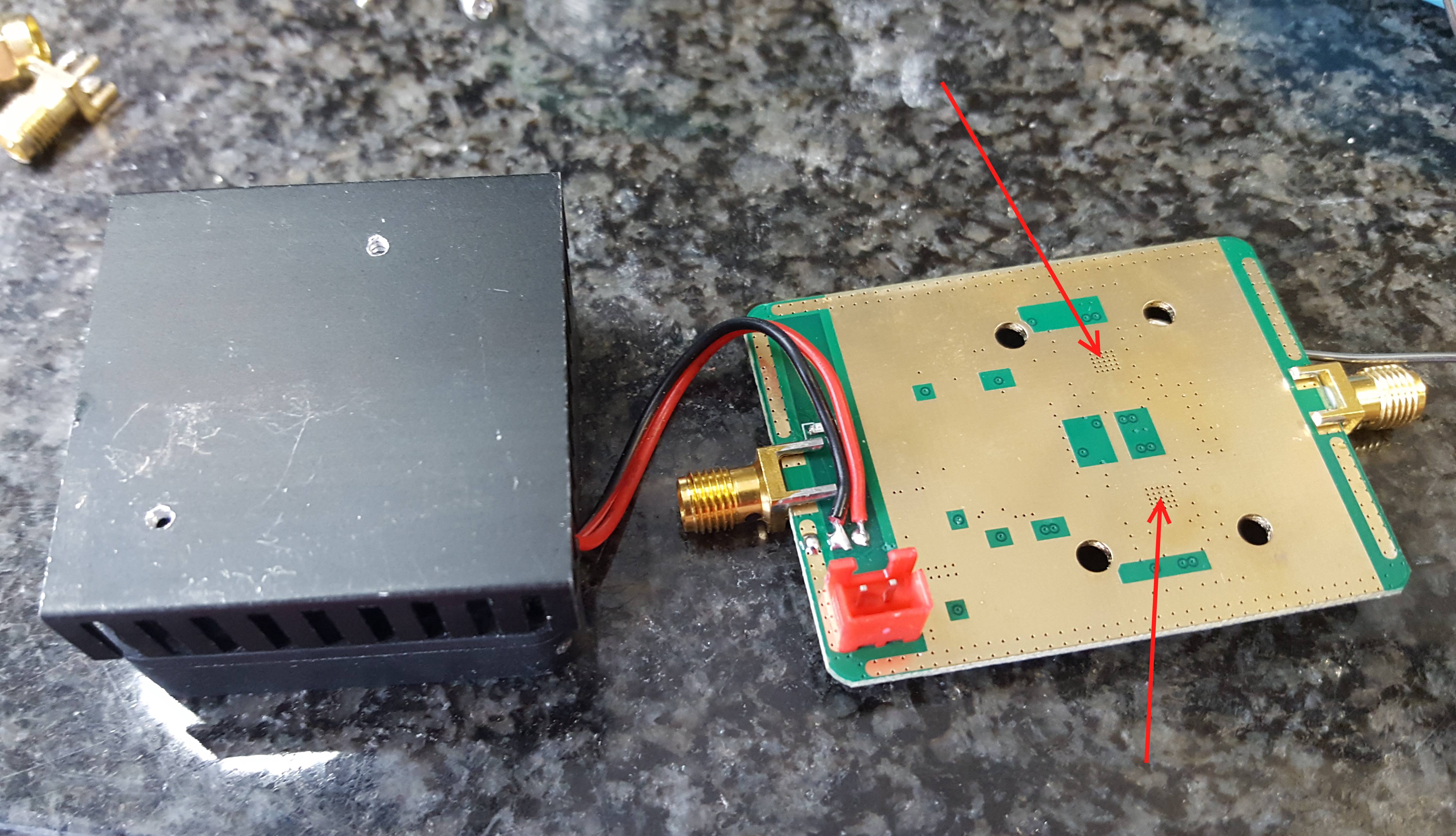
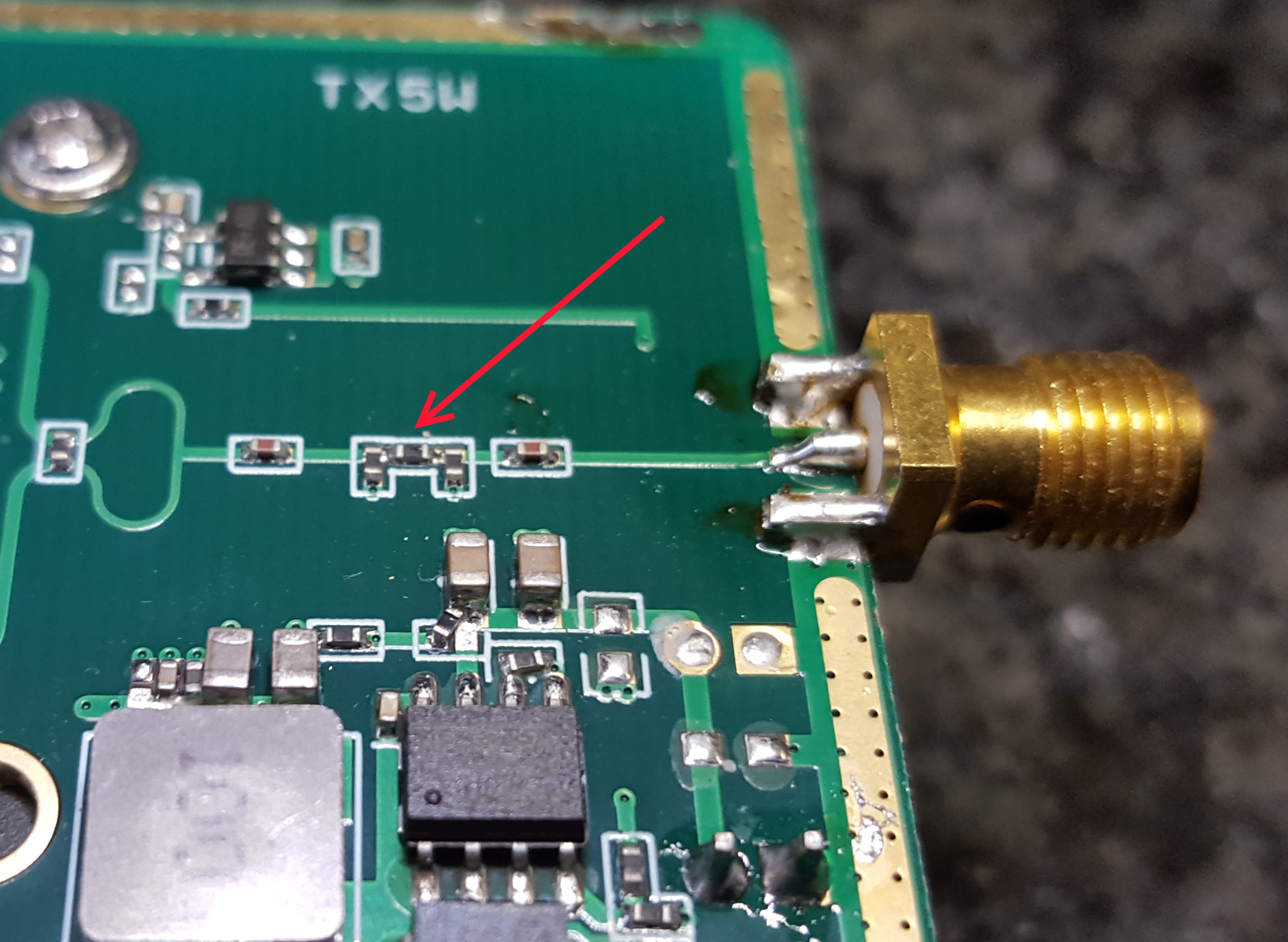
For 13cm my transverter masthead box with the 75W amplifier was used. Its the same that was already used first last year. Together with a PTT splitter it was possible to connect my old 5W 9cm system to the same 1m dish as well. This was working better as expected.
On 6cm we had a very well working system with a old IC202 as IF transceiver. Despite not beeing used for quite some time it was still doing great.
For 3cm the feed was missing unfortunately and so we skipped the band entirely.
Surprisingly all systems where up and running at the beginning of the contest.
The focus was planned to be on 23cm because this band counts for the DARC CM. All other bads where add-on for the DARC UKW Contest Pokal OV competition.
23cm right, 13/9cm and 6cm left.
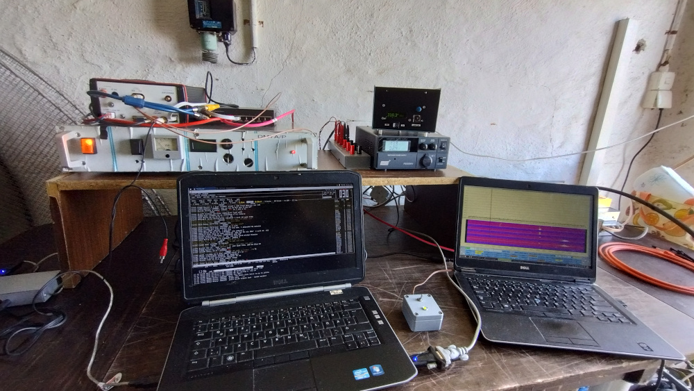
23cm place with SDR PC right and log left.
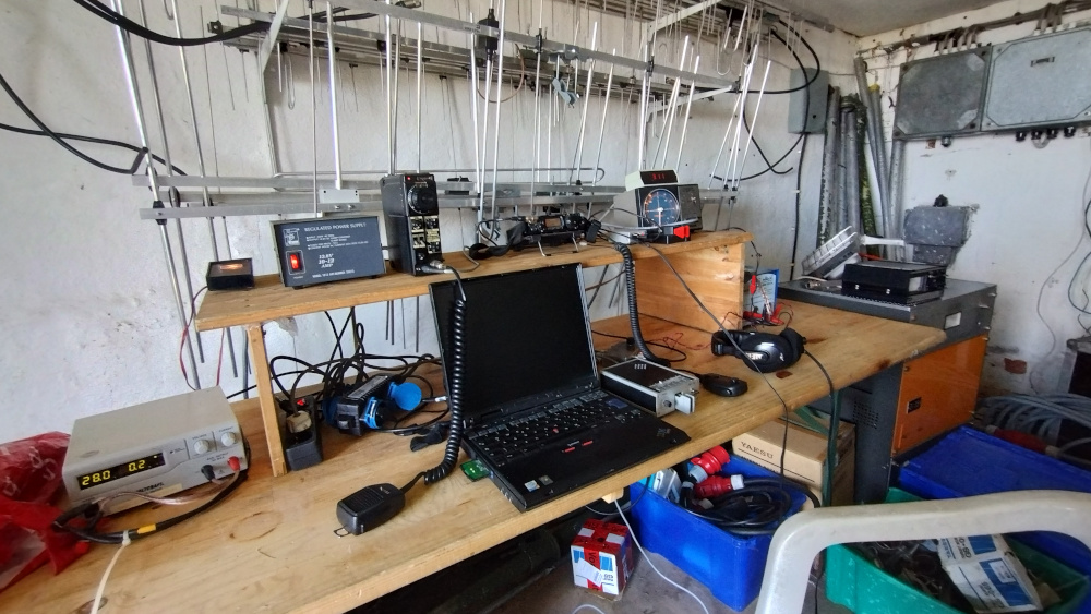
place for 13, 9 and 6cm operation.
The activity saturday afternoon and sunday morning was quite good. But i had some impression that the activity from OK which was always great is somewhat declining in the recent times. Its a bit compensated by the IC9700 effect.
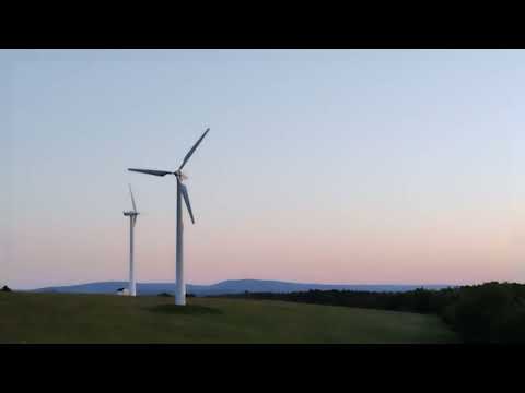
In addition to the microwave activity i was planned in for some lightwave tests saturday evening. Jo DL3ARM does a great job motivating an increasing group of enthusiasts to try communication with visible light. So i took my old laser station to the hill. The decision was absolutely good since the weather turned out to be almost perfect.
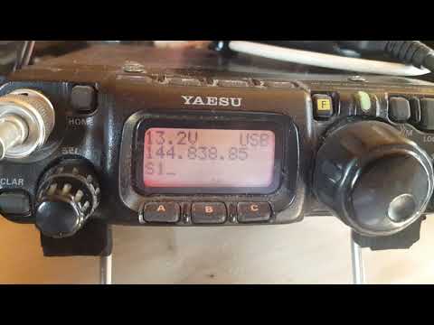
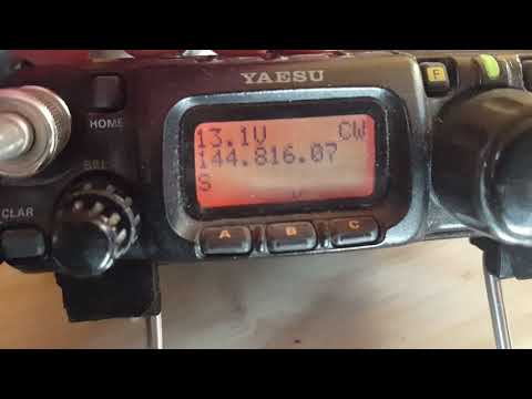
Jo was on the Fichtelberg JO60LK which is only about 20km from our location. We found each others light very fast and completed the QSO in AM within minutes even during the sunset. It was great to hear his modulation and i think it was my first voice QSO via light. I took a short video of his on-off beacon signal demodulated at my station. The loud noise is some 70cm APRS on the talkback frequency we had choosen.
The next foto shows my red light as seen by Jo DL3ARM on Fichtelberg.
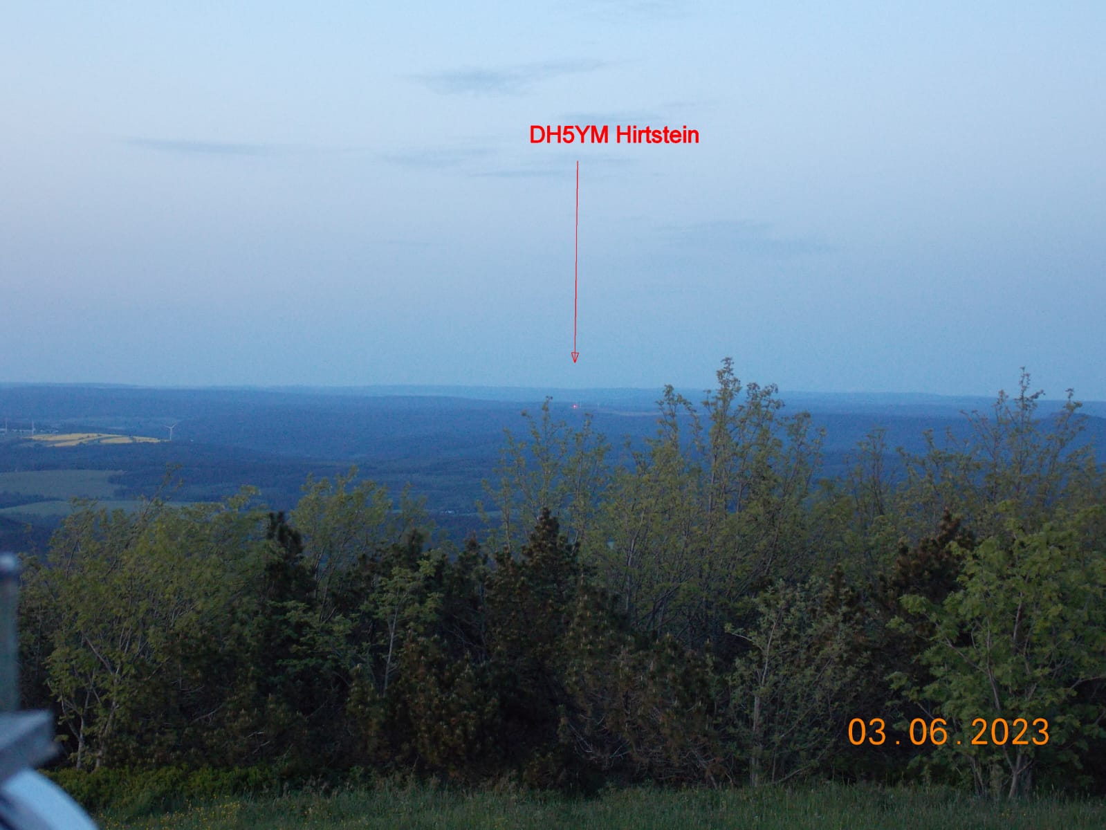
My light from JO60OM as seen by DL3ARM in JO60LK
After that QSO i had an unsucessful attempt with DM5D (Wetterberg) and DL3ALF (Trageser Halde). During investigations later the next week i found that the path to DM5D is unlikely to work due to going through trees in between. But the path to DL3ALF should have had perfectly worked. The problem was likely that our preparation had room for improvement. From Trages you cant see the chimney in Chemnitz which is a prominent landmark due to its colorful lighting in the night. This and the cold wind and darkness on the tower there makes it very diffcult to find the right direction. Therefore we missed this slot.
The path to DL0MLU on the Petersberg close to Halle seems too far as well. But one more QSO i was happily able to complete. With DR7B (Rene DL2JRM) i was able to complete a very nice 65km AM QSO after some minutes of mutual searching the horizont. This was a new light ODX for myself and i am very happy about that. Unfortunately i missed to take a video :(
After storing away the light rig i continued with 23cm to about 0030UTC. Then there was nobody to contact anymore in the ON4KST chat and i decided to take some sleep. I only started operation again from lunch to the end of the contest.
The result with claimed scores is:
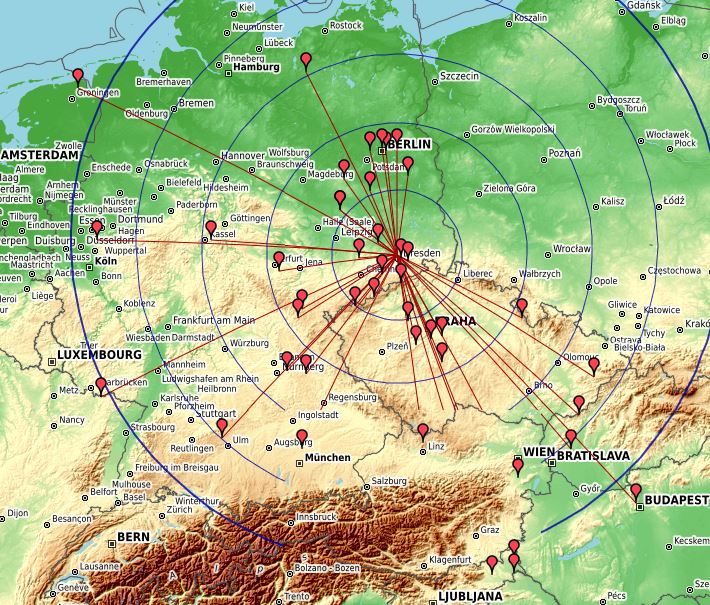
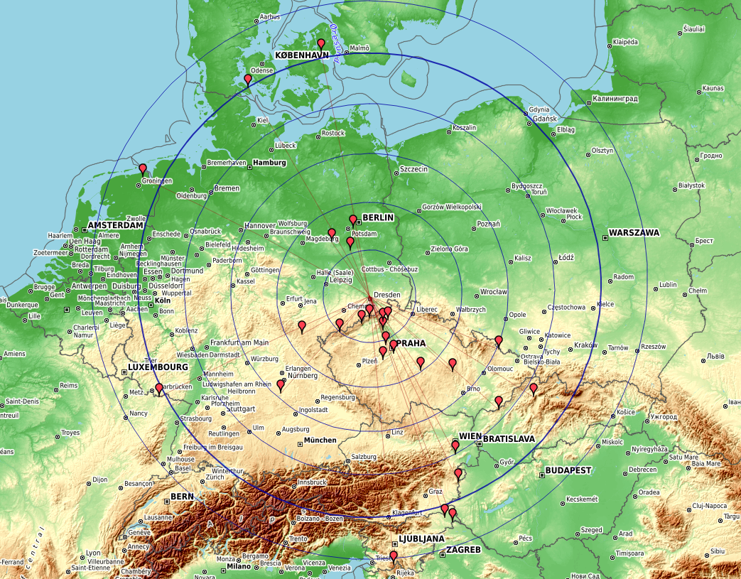
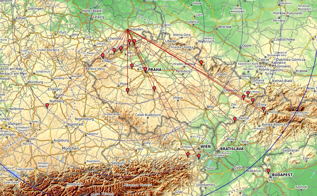
23cm: 89 QSO (some dupes), ODX HA8V 680km => 3rd in DL SOP
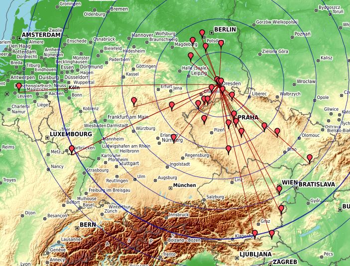
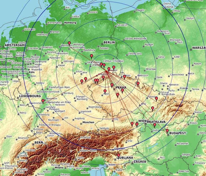
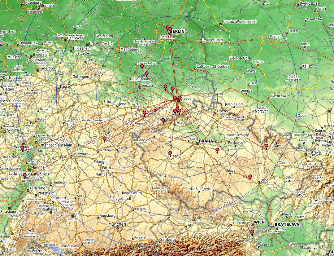
13cm: 25 QSO, ODX ON4CJQ/P 580km => 4th in DL SOP
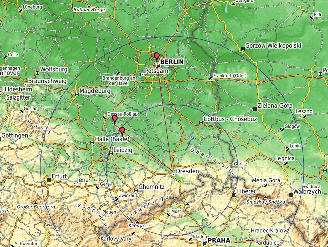
9cm: 14 QSO, ODX OE5VRL 240km => 4th in DL SOP
6cm: 10 QSO, ODX OE5VRL 240km => 1st in DL SOP
Light: 2 QSO, ODX DR7B 65km => 2nd in DL SOP
Next time will likely be only some QSO from home in July.
Some maps:
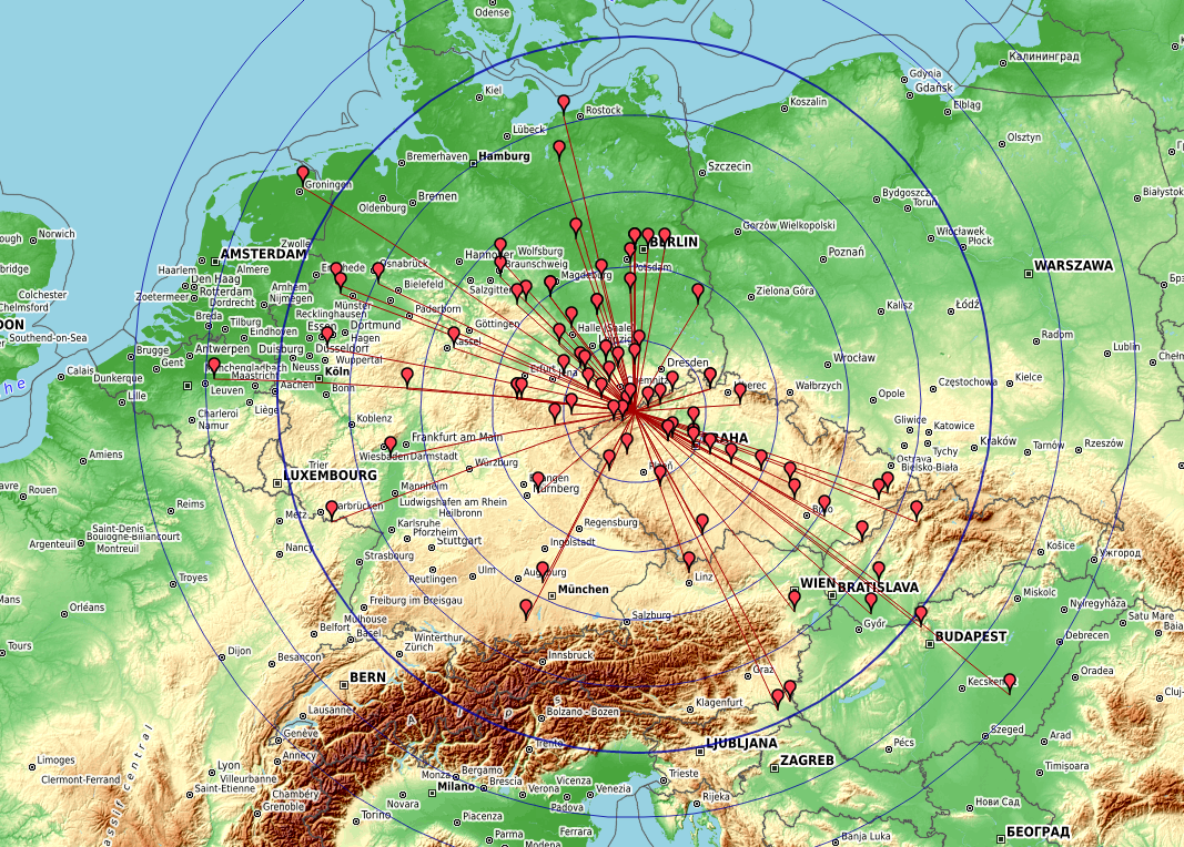
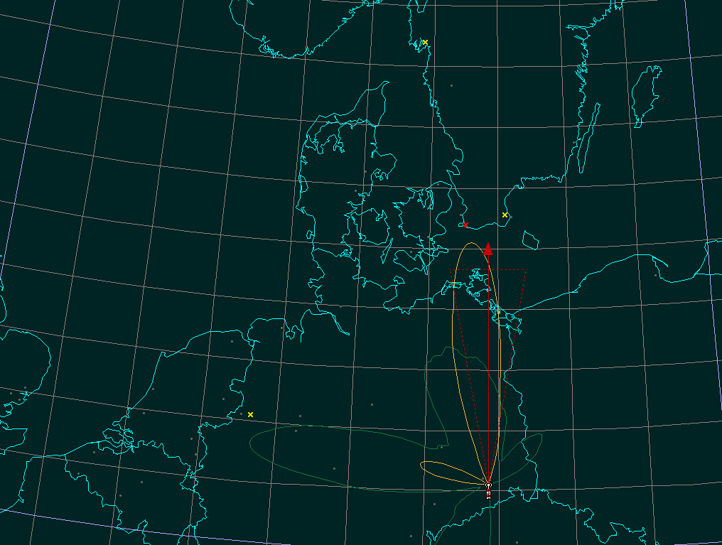
23cm 23/06 – Kartendaten: OpenStreetMap-Mitwirkende, SRTM | Kartendarstellung: OpenTopoMap (CC-BY-SA), DL4MFM log analyzer
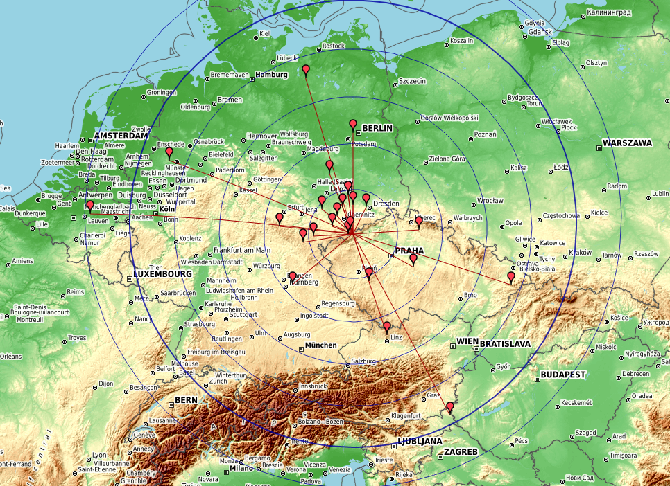
13cm 23/06 – Kartendaten: OpenStreetMap-Mitwirkende, SRTM | Kartendarstellung: OpenTopoMap (CC-BY-SA), DL4MFM log analyzer
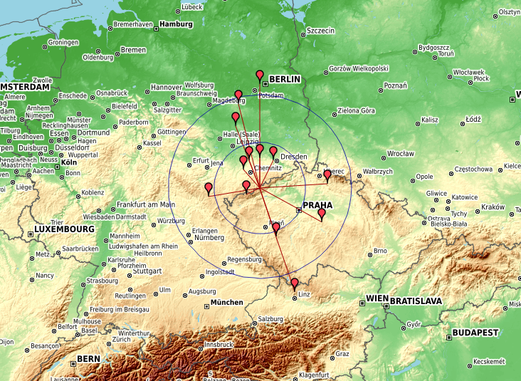
9cm 23/06 – Kartendaten: OpenStreetMap-Mitwirkende, SRTM | Kartendarstellung: OpenTopoMap (CC-BY-SA), DL4MFM log analyzer
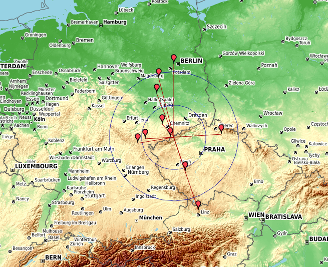
6cm 23/06 – Kartendaten: OpenStreetMap-Mitwirkende, SRTM | Kartendarstellung: OpenTopoMap (CC-BY-SA), DL4MFM log analyzer