Over a year ago i started building a little sequence control unit for transverter usage. The PCB i showed already here. Unfortunately i made a stupid beginners mistake and used a package that does not belong to the footprint. So the first PCBs can be just brought to life with a bunch of patch wires.
Now i found some time to bring the microcontroller firmware to a usable state and made a short video of operation.
The schematic you can find here:
Please notice that the attiny package shown in the schematic belongs to the package without leads which is not the one on the board !
The sequencer has a lowside switch for RXTX relais control and a highside switch for PA supply control as the sequencers from DB6NT have. In addition there is a TX_INHIBIT output that can be used to prevent your Yaesu radio from transmitting until the sequencer has switched to TX entirely. Alternatively you can use it as PTT signal for your transceiver. And there is a kind of “sequencer active” signal that only switches to ground if the sequencer is in TX state (in the schematic its named ERR_OUT but i used it for this function now).
In contrast to other sequencers this one has an error input. If this input is keyed down only the RXTX relais is switched on and the rest of the functionality is locked (means the sequencer cannot switch to TX anymore). It is necessary to release the error input and the PTT to get back to RX state. Together with the “active” output this can be used to lock several transverters against each other for example if they are used with a common dish.
In addition i equipped the board with a ULN2003 darlington array that can be used as 7 port lowside switch to realize further switching outputs.
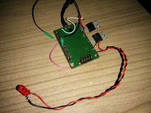
As i told before a somehow messed up the layout. Thats why i do not publish it here. If there is some interest i can update it to the correct package and make it available. However i show some more pictures of the prototype unit.
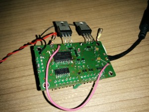
In the second pictures you see the necessary patchwires. Fortunately GPIO are software configurable ;)
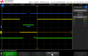
Switching behavior is normal for a sequencer. The yellow line is PA relais output, the green line is the PA supply voltage, the blue line is the TX_INHIBIT output. The PTT input signal is not shown here but was asserted from start of relais until the TX_INHIBIT signal goes high again.
Further ideas for the circuit are welcome. Some i already got. E.g. controlling rotary RF switches. I will look into that.


