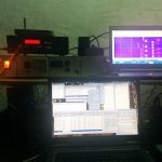
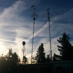
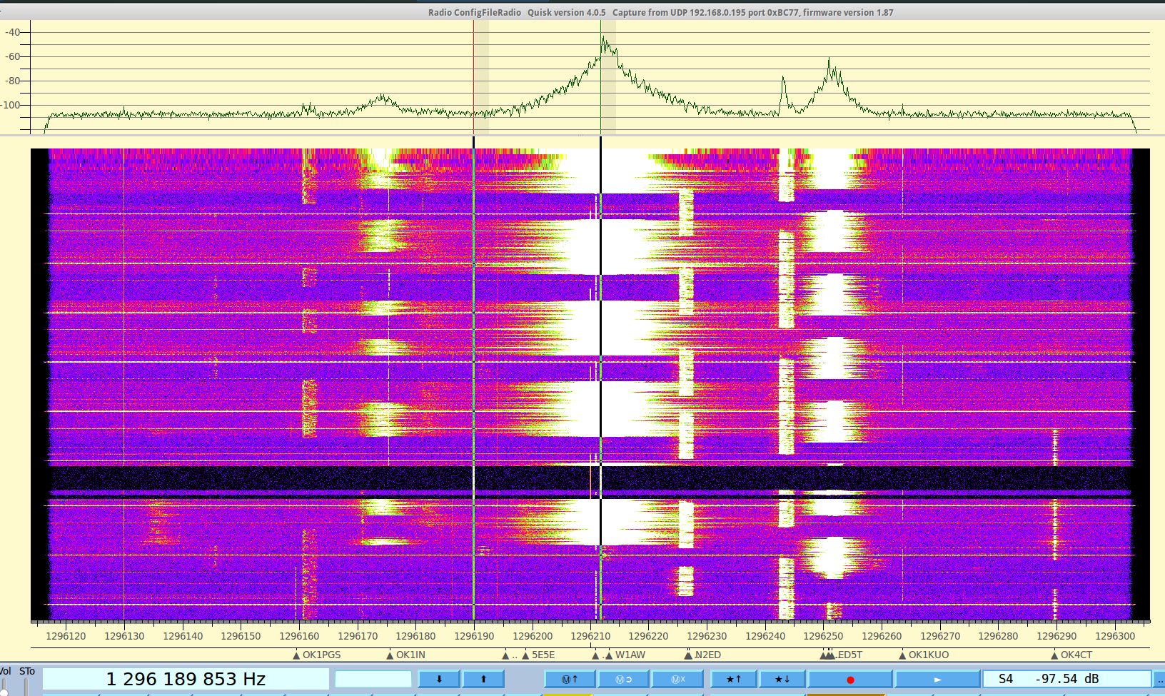
I was not qrv from JO61XA for a long time. Now there was the chance to take all the equipment to Triebenberg again. During the last months i tried to repair some things here and there. The 9cm transverter got a new alignment and is working now. Saturday morning i collected all the stuff and partly assembled it. I wanted to go for 23/13/9cm and 3cm eventually. This time i used the 1m dish that i bought last year in order to save some time during the mast construction. In the end i was qrv 1 hour after beginning of the activity. So what… The goal is to test the hardware. First observations were not that promising: 1) bad connection of the DC supply for the mast transverters 2) control unit for the rotator was not working.
The later one was really bad. Later at home i noticed that i partly disconnected the cable for the display / keypad unit when fixing some loose screws few weeks ago.
For 3cm i picked a second IF transceiver. Unfortunately the wrong one. The IF is 432MHz but i took the FT-290 instead the 790R2 ;) RX/TX switching via the mimic for the 2m based transverters from the FT-817 was not working but it took me almost until end of the test to find out what was going on. So only 1 QSO there.
Also 23cm seemed to have some oscillation in the RX LNA. I got some very strange sounds from time to time when releasing the PTT. Maybe some feedback from the 13/9cm transverters because of the PTT mimic i use (i switch all chains to TX but only transfer the IF to the one i want to use. Decoupling is only 50dB which might be an issue. I need to investigate there).
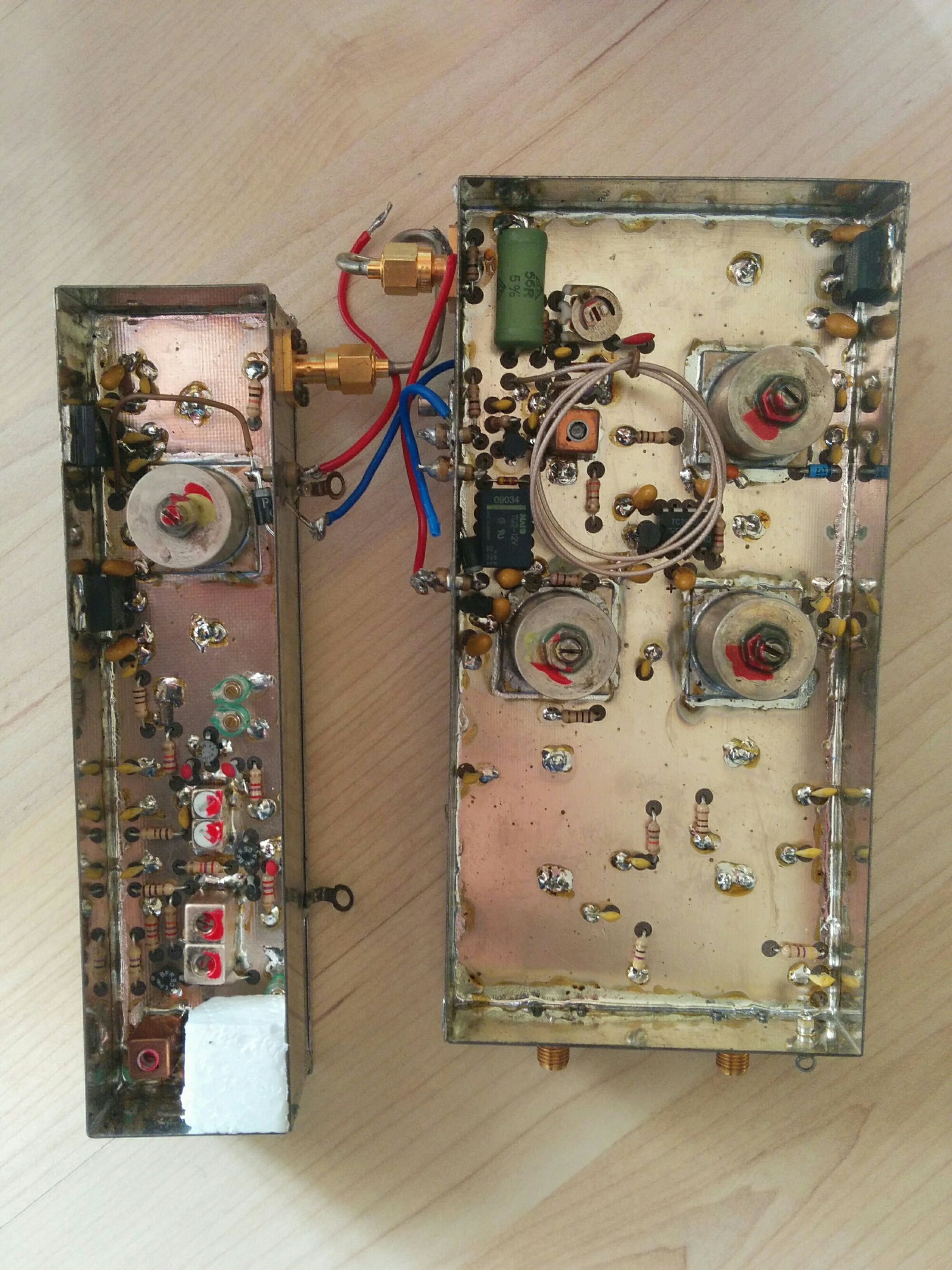
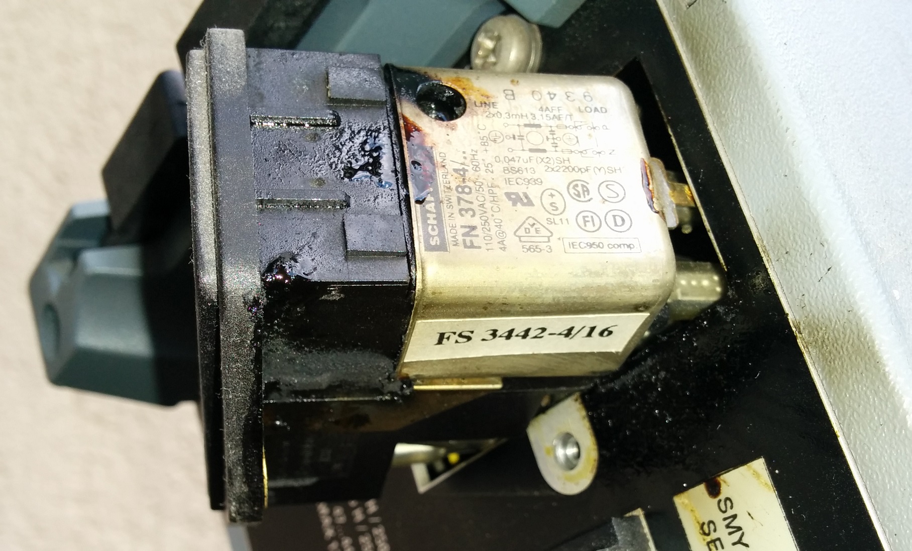
Finally, when deconstructing the mast, i was a bit optimistic on the way to remove the ropes and had a very robust takedown of the antenna and transverters. The main impulse was taken bei the box of the 13cm transverter. Fortunately only the plastic box splitted into several segments. The transverters are still working fine… lucky operator ;) I anyway want to put it into a common box with the 6cm i am going to build and the new 9cm i have flying around as components here.
Hope to hear you again next time.
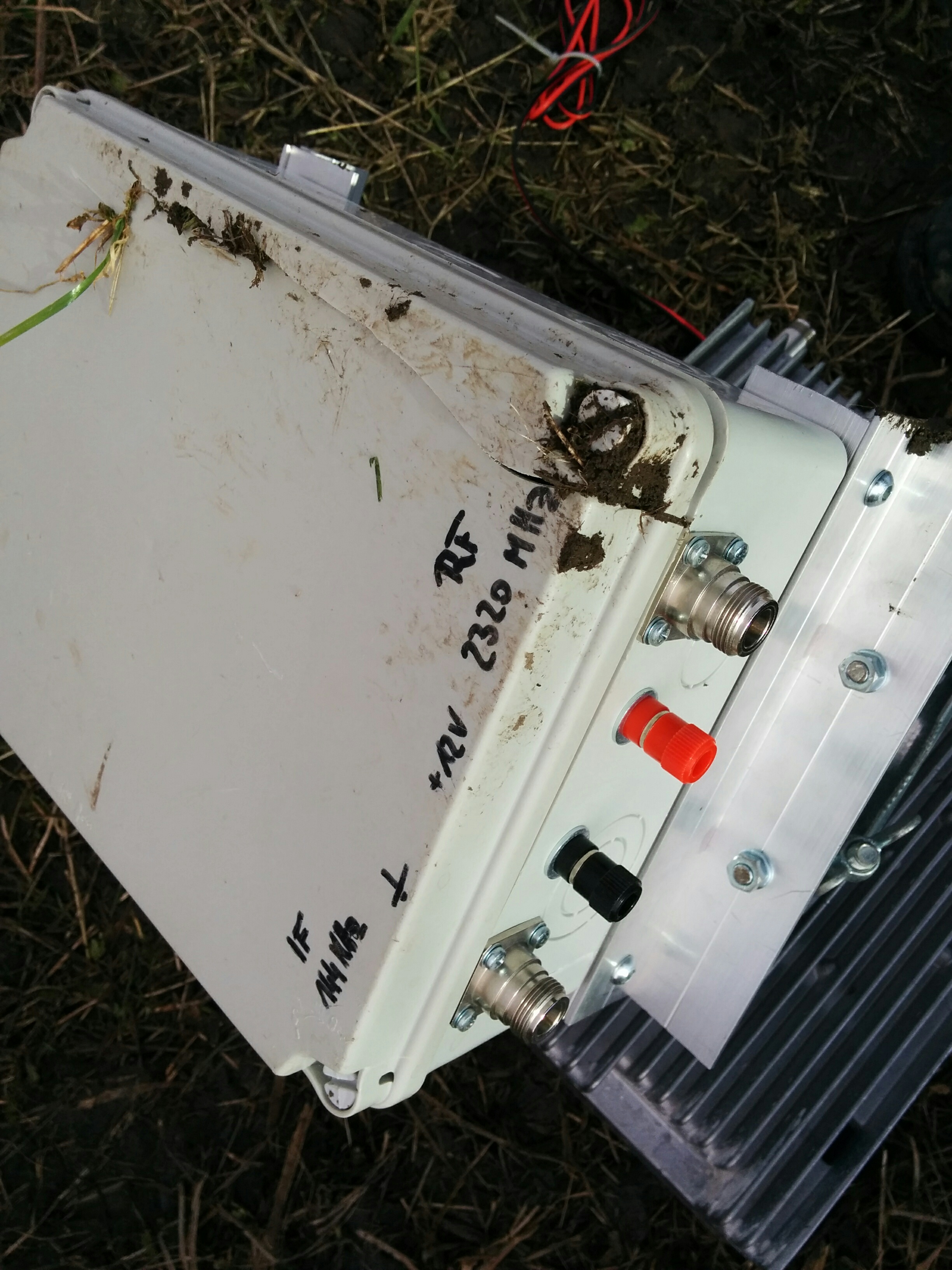
damaged 13cm transverter box