RX/TX sequencer new PCB from China

2nd version of the PCB i designed over 2 years ago. Hopefully without bad errors i hope ;) Lets see when the shipment will arrive…
I corrected the package of the microcontroller and swapped a few signal pins in order to gain some flexibility with the software.

Sequencer version 2 PCB

GPS 10MHz reference

Since some time i own a DF9NP GPSDO. Currently i only use it to lock my signal generator but i also want to use it for my microwave transverter OCXOs. When connecting a SMIQ signal generator and checking the signal output at 6GHz i noticed some +-50Hz jitter under the poor reception conditions at thelocation of this signal generator. So i want to look a bit closer into that topic. In China i ordered a Neo-M8N module that can be configured to provide a 10MHz clock at its timepulse output. I tried to compare it with the GPSDO and the OCXO of my SMY-02 signal generator.
Of cause the digital clock has significant jitter because it is generated by a CPU (specified with +-10ns).

Neo-M8N clock output at 10MHz

The picture of the timepulse at 10MHz shows, that it seems that comparing the clock to a stable oscillator over a relatively short period could be sufficient for adjusting the frequency of this oscillator to the GPS.

GPSDO, M8N, OCXO

The screenshot shows the oscilloscope triggered to the GPSDO (green). The output of the M8N module (yellow) shows the jitter and the adjustment range within 60 seconds (yellow shadow). The third (blue) trace comes from my SMY-02 which was locked to the GPSDO. The SMY signal shows some slight jitter compared to the reference. To me it is not clear if the cause is the reference or the locking in the generator. The clock from the M8N module shows significant adjustment of the clock frequency within the 60 seconds shown compared to the GPSDO which has a TCXO that is slowly compensated by the GPS inside the reference.
Looking to the signal in frequency domain shows this picture:

Neo M8N spectrum

There are rather close sidebands that require narrow band adjustment of a oscillator eventually locked to this GPS clock. Wideband the spectrum is noisy as well.

M8N phasenoise at 10MHz

Finally i took a short video showing the the scope triggered to the 10MHz OCXO reference of the SMY and comparing the GPSDO and the M8N output. The OCXO is slightly off 10MHz and therefore the picture is moving all the time. You can also see that the M8N is slowly adjusting compared to the GPSDO output.

GPS 10MHz GPSDO vs Neo-M8N and 10MHz OCXO

9cm transverter

9cm Transverter

The above shows my 9cm transverter. It gives about 5W in 3400MHz. The boxes are rather old but still work fine after adjustment of all currents. The PA has 46dB gain which makes a attenuator necessary. 

transverter component side

This photo shows the assembly side with the RF transistors. The other side carries the filter cups aß Well as some other larger components.

transverter top side

The small box ist the oscillator/multiplier and the other one the transverter.

OCXO G8ACE phasenoise & startup

G8ACE OCXO at 103.5MHz

103.5MHz oscillator briefly measured with R&S FSP30..

PN Plot G8ACE OCXO

I think above 1kHz the PN figure is determined by the FSP oscillator.
Does someone have a better measurement of such an oscillator, especially above 1kHz up to 200kHz ? Unfortunately i do not have a better PN testset.

The following picture shows the cold-start behavior of the OCXO from room temperature to 60 degree celcius. The X-axis shows time in seconds and the y-axis frequency in Hz.

G8ACE OCXO Startup

Attiny RX/TX sequencer

RX/TX Sequencer with Attiny

Sequencer for Transceiver and Transverter sequence control made around a Attiny2313. It can switch a RX/TX relais lowside, a PA supply highside, has “active” and a “TX inhibit” outputs. Furthermore there is a input to lock the PTT from a second sequencer (switch on the RX/TX relais only). There is an extra 7bit output driver that is in that example used to drive a pulse controlled RF relais.

Burned mains filter

Last weekend i had a negative surprise. Some noise from the desk and a lot of fume indicated that some electronic stuff burned.
Investigating the source of the fume i found that the mains filter of my old R&S SMY-02 burned away.
Fortunately i have connected it to a switchable mains distributor which prevented it from burning in my absense.

burned mains filter of SMY-02

burned mains filter of SMY-02

Attiny2313 based sequence control

Over a year ago i started building a little sequence control unit for transverter usage. The PCB i showed already here. Unfortunately i made a stupid beginners mistake and used a package that does not belong to the footprint. So the first PCBs can be just brought to life with a bunch of patch wires.

Now i found some time to bring the microcontroller firmware to a usable state and made a short video of operation.

Attiny sequencer

The schematic you can find here:

attiny sequencer schematic

Please notice that the attiny package shown in the schematic belongs to the package without leads which is not the one on the board !

The sequencer has a lowside switch for RXTX relais control and a highside switch for PA supply control as the sequencers from DB6NT have. In addition there is a TX_INHIBIT output that can be used to prevent your Yaesu radio from transmitting until the sequencer has switched to TX entirely. Alternatively you can use it as PTT signal for your transceiver. And there is a kind of “sequencer active” signal that only switches to ground if the sequencer is in TX state (in the schematic its named ERR_OUT but i used it for this function now).

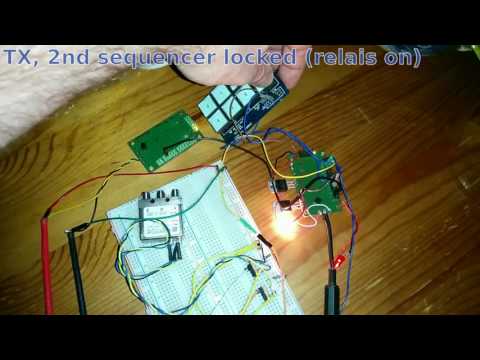
In contrast to other sequencers this one has an error input. If this input is keyed down only the RXTX relais is switched on and the rest of the functionality is locked (means the sequencer cannot switch to TX anymore). It is necessary to release the error input and the PTT to get back to RX state. Together with the “active” output this can be used to lock several transverters against each other for example if they are used with a common dish.

In addition i equipped the board with a ULN2003 darlington array that can be used as 7 port lowside switch to realize further switching outputs.

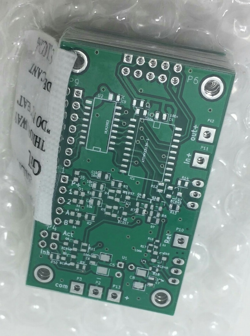
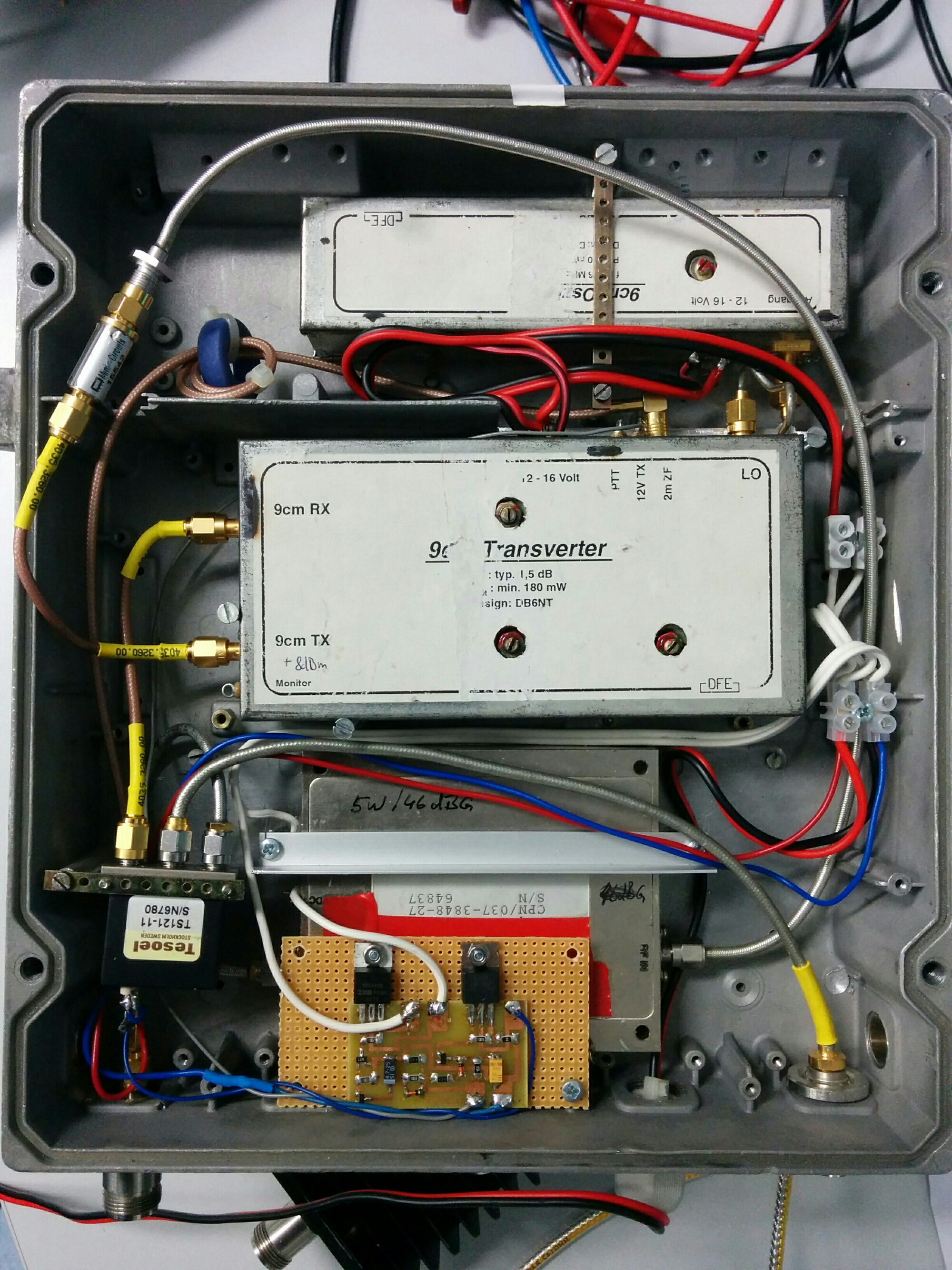
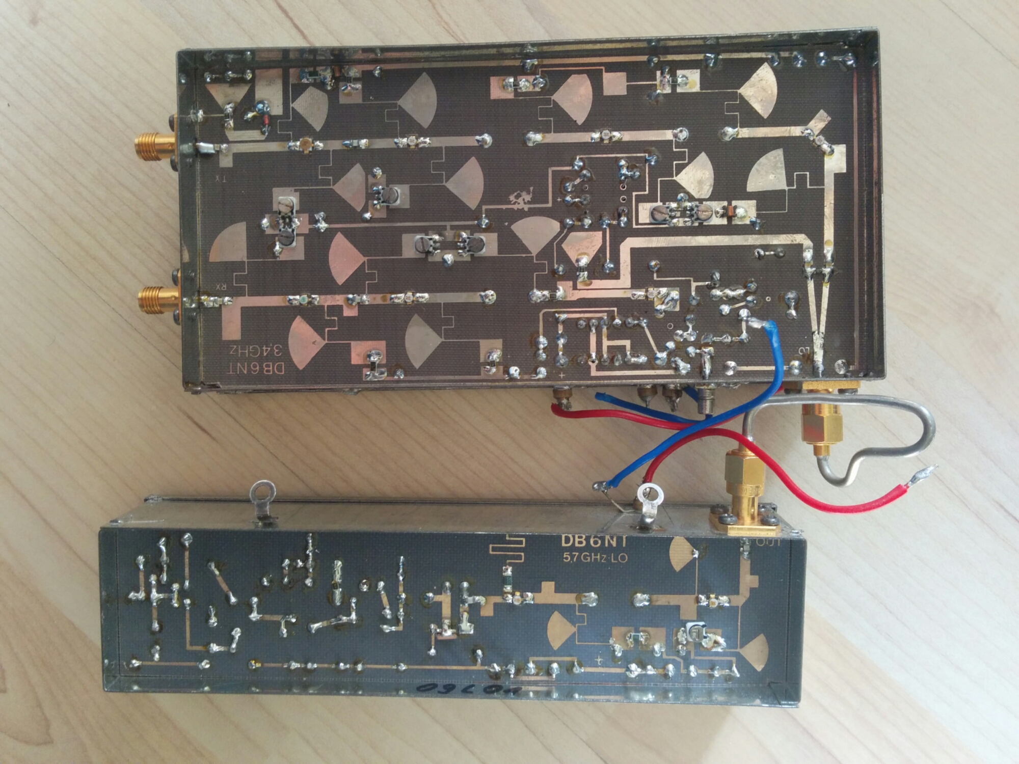
As i told before a somehow messed up the layout. Thats why i do not publish it here. If there is some interest i can update it to the correct package and make it available. However i show some more pictures of the prototype unit.

top side - LED at the PA output, lamp at the relais output

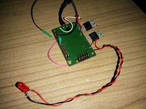
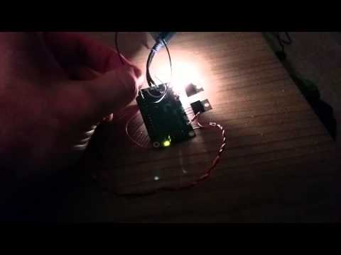
top side – LED at the PA output, lamp at the relais output

bottom side - attiny2313, uln2003, few transistors, diodes, ...

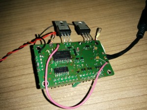
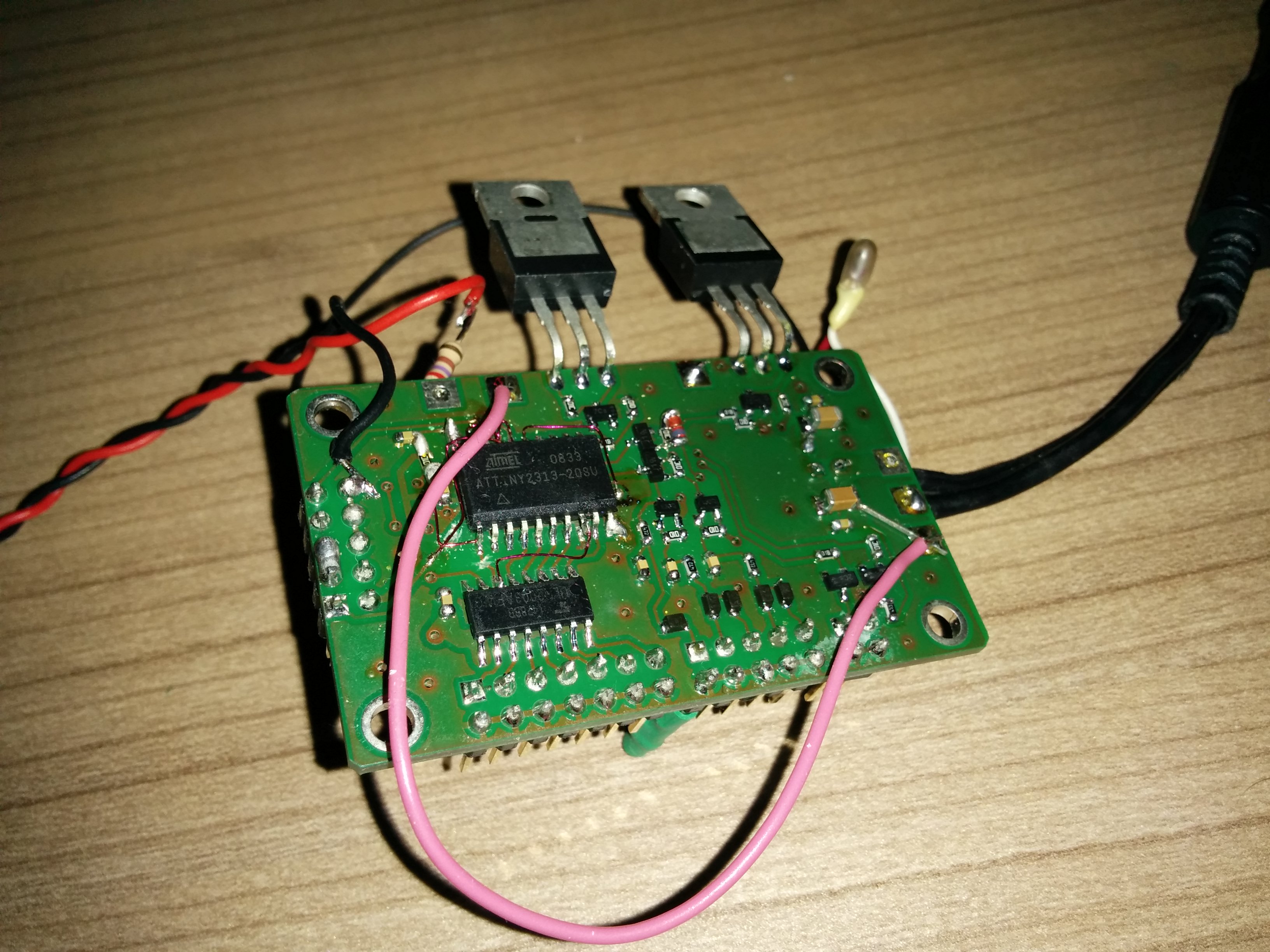
bottom side – attiny2313, uln2003, few transistors, diodes, …

In the second pictures you see the necessary patchwires. Fortunately GPIO are software configurable ;)

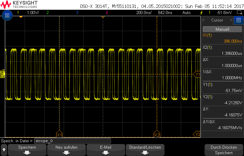
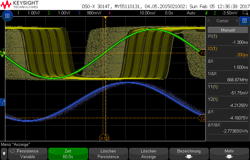
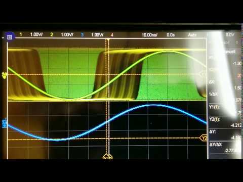
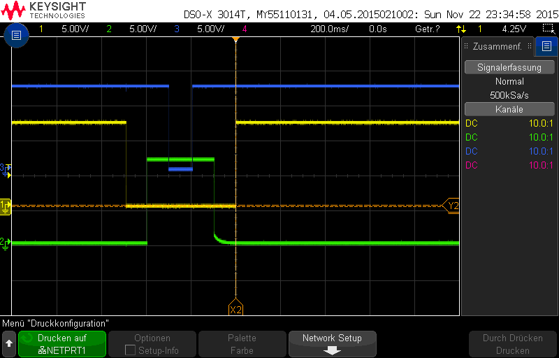
Switching behavior is normal for a sequencer. The yellow line is PA relais output, the green line is the PA supply voltage, the blue line is the TX_INHIBIT output. The PTT input signal is not shown here but was asserted from start of relais until the TX_INHIBIT signal goes high again.
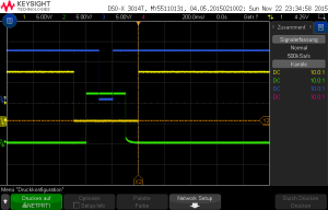
sequencer switching

sequencer switching

Further ideas for the circuit are welcome. Some i already got. E.g. controlling rotary RF switches. I will look into that.

DL6GL fan control

From time to time temperature dependent control of fans is required. At Georg’s DL6GL page i found a nice analog solution. He constructed a circuit with TL081 and NTC. I decided to build 4 pieces. (thanks to DG2DWL for etching the boards)

The switch temperature and the hysteresis can be controlled by the 2 adjustable resistors. In the middle you see the NTC, just soldered for a quick test.

Details you can find on Georg’s page:

http://dl6gl.de/selbstbau-trx/der-tx-signalpfad/temperaturgeregelte-lueftersteuerung

DL6GL fan control

DL6GL fan control – 1 sided PCB

Tiny Sequence control unit (WIP)

image

Thats a simple sequence control unit for transverters etc. ON a double layer PCB. The design was eine with the open source tool KiCAD. Its made around a attiny2313 and features a highside switch, a lowside switch as well as a uln2003 driver. In addition further sensors can be connected via I2C or SPI. The software is not finished. More information will follow.