I have a Tytera MD380 DMR transceiver now. Flashed latest MD380tools and database yesterday and hope to make a first qso soon. A mmdvm hotspot is in the pipeline but i still need to connect a transceiver.
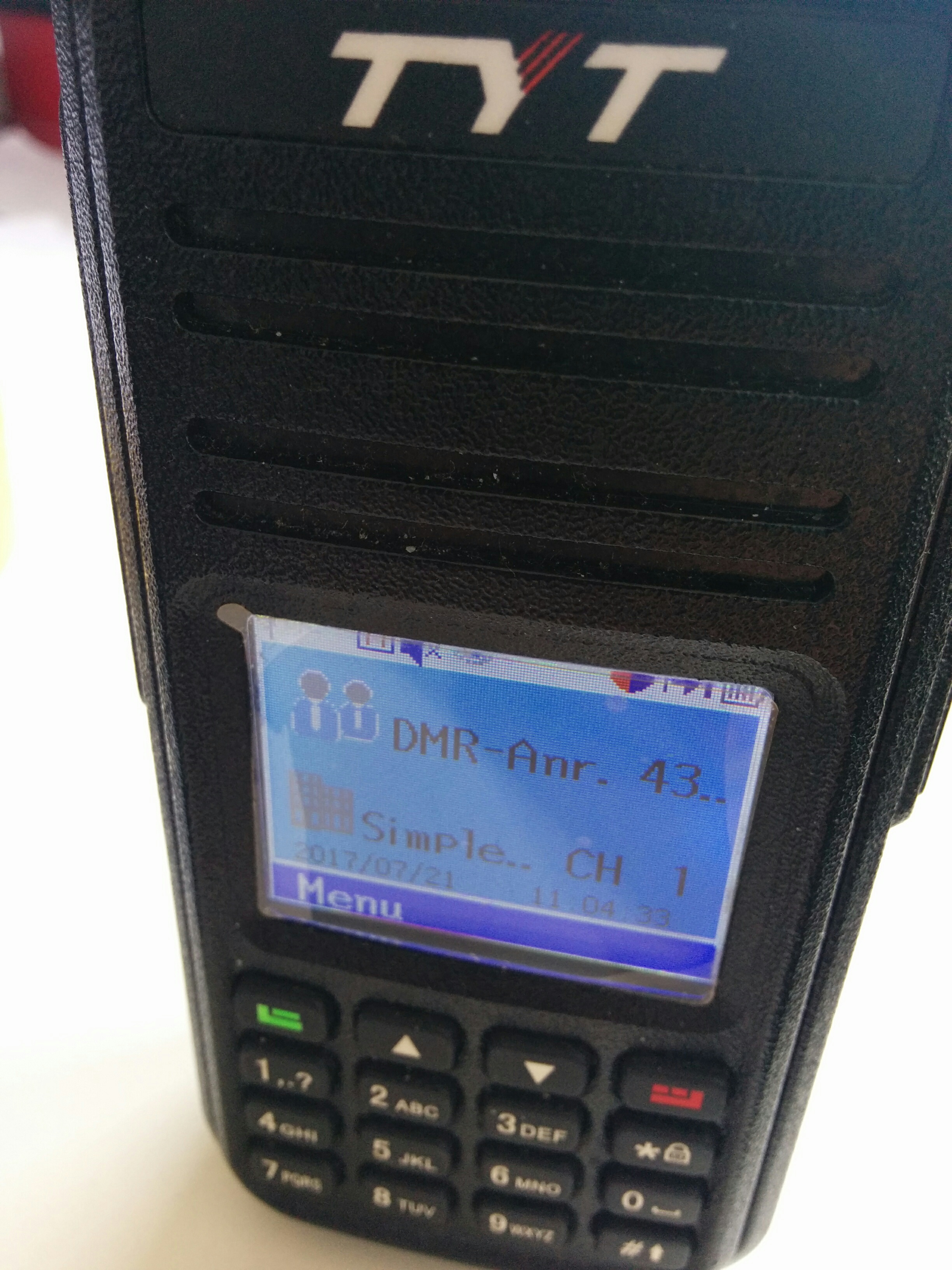
TYT MD380 DMR radio

I have a Tytera MD380 DMR transceiver now. Flashed latest MD380tools and database yesterday and hope to make a first qso soon. A mmdvm hotspot is in the pipeline but i still need to connect a transceiver.
TYT MD380 DMR radio
I tested my new assembled wideband high IP amplifier (BX-088) from Funkamateur. The transformers need to be handmade which is a very fiddling task. The cores are really small. I choose for 11dB gain assembly. The measurement shows, that the gain really rapidly drops below the 160m band. The figure fits to what is shown in the documentation. So far i did not measure the p1dB or IM3 behavior.
The points that are interesting for me are 28MHz as LNA for my SDR or as IF amplifier for transverter input on 14/28MHz and usage as pre-amp for 70MHz.
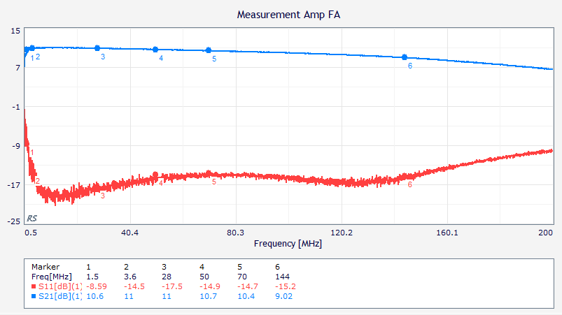
Measurement of Funkamateur wideband amplifier
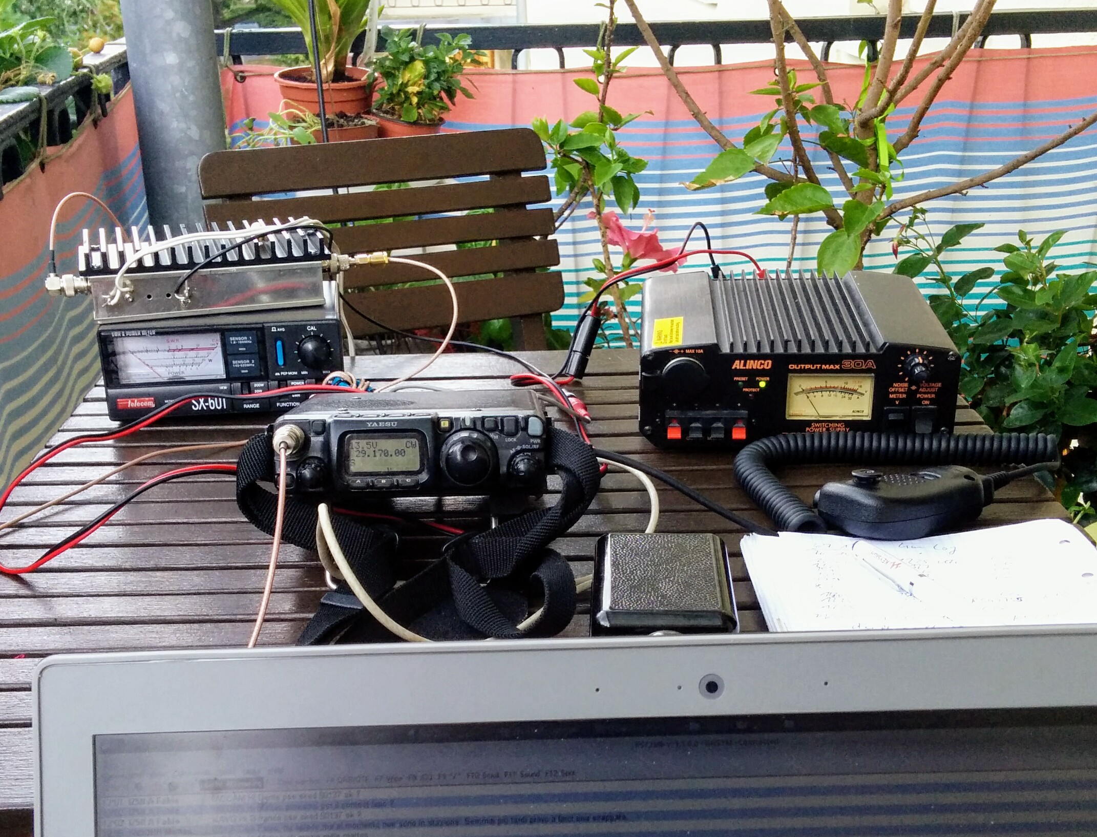
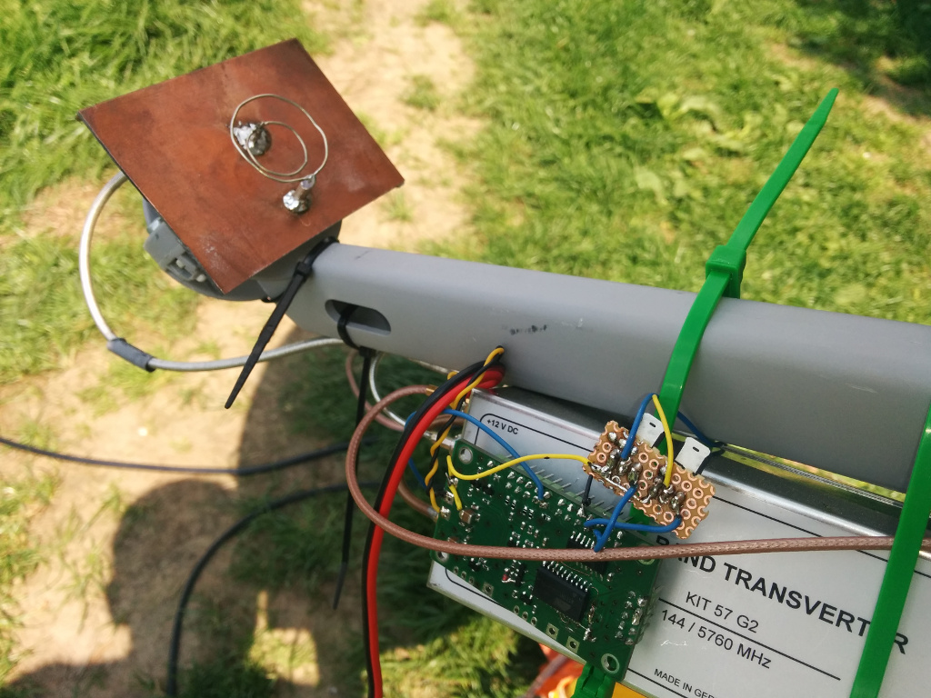
Now finally i have my 4m rig ready. It consists of a DF2FQ transverter with some modification to power module mounting and RX amplifier stage.
Currently i use my FT-817 to drive it. I also added a separate drive input which i need for the SDR. With 1mW input on 29MHz it can achieve about 25W output on 70MHz.
So far i did not benefit from ES conditions. Seems it missed all the nice propagation from last weeks. Hopefully there will be another opening until end of August, when the permission ends here.
As antenna i use a Hentenna Quad with direct 50Ohm assymetric feed point. The antenna has some significant Null in the radiation pattern but is a good compomise for the fibre mast at the balcony.
My fist contact was with DK2EA in JO50UF in CW. Meanwhile i also worked DD1VD and DL2VPO locally.
4m band rig on the balcony

4m Hentenna Quad
[Edit 2017/07/23] meanwhile i worked EA1BFZ in IN81SS and today SV2JAO in KN10DN. ES propagation seems to be very short and spotty. You really need to look to the cluster and search the frequencies all the time. 5 minutes later all could be gone. 100km away the conditions can be significantly different.
This year i was on vacation again during the June DUR weekend.
So i took the 23cm transverter + FT-817 + my 16ele Yagi with me to do some aircraft scatter QSO.
My location was balcony on the 8th floor but with decent takeoff towards JO60/61. Takeoff more towards west was slightly better.
Looking to the Airscout software revealed very few planes. This resulted in weak and very short reflections. In the end 3 QSO. Best signal was from DJ5AR this time which was the most distant QSO.
Unfortunately i found no other station for a QSO in the north.
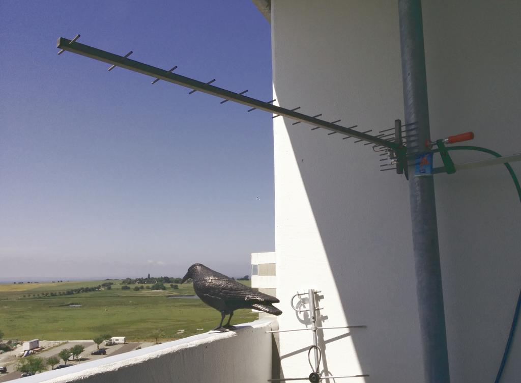
Antenna mounted to rainfall pipe. Baltic sea in the background.
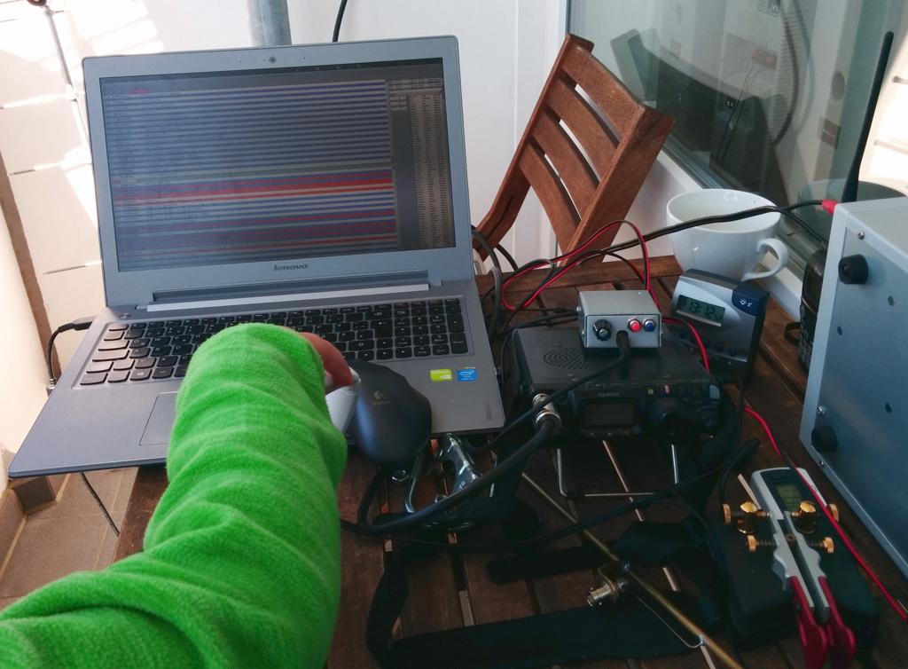
my portable station. You can see the arm of my 3year old co-op “operating” the chat PC ;)
I was searching for some simple LNA for microwave reception and found a very cheap board from China. For less than 10 Euro i ordered a LNA board that is specified to work from 50MHz to 6GHz. The gain should be about 20dB at 50MHz and still >10dB at 6GHz. Even if it does not work like that the PCB with shield and SMA jacks is still a good deal. You can find some measurement results below. The original condition makes clear that the gain on the upper frequencies is not good. Touching the bias network with the finger showed slight improvements. So it was clear that there is some problem with the components feeding the MMIC. Exchanging the ferrite bead by a 68nH RF coil gives much better results up to 4.5GHz but still has problems on the highest frequencies. So i tried a 2.7nH i series directly connected to the RF trace in order to avoid the stub that was there before. Now 6GHz is good but there is a resonance at about 3.5GHz. My last attempt was an additional 120nF to ground between the two coils. Thats pretty promising for the microwave bands but below 800MHz the LNA is not usable anymore. So the network still has room for improvement but it is at least clear that the board is usable.
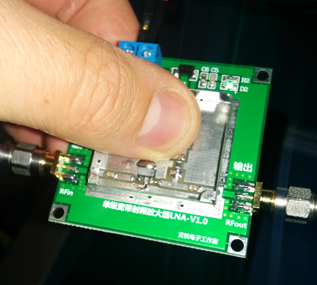
Chinese LNA with german finger ;)
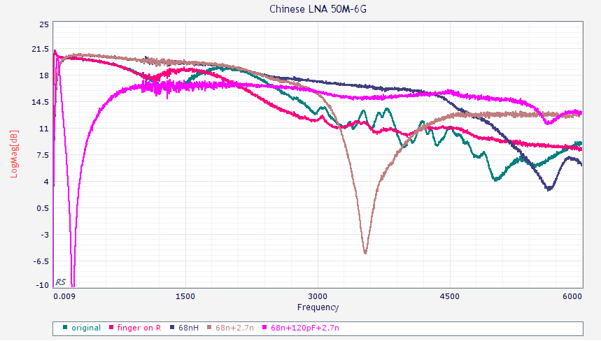
measurement results for different bias networks
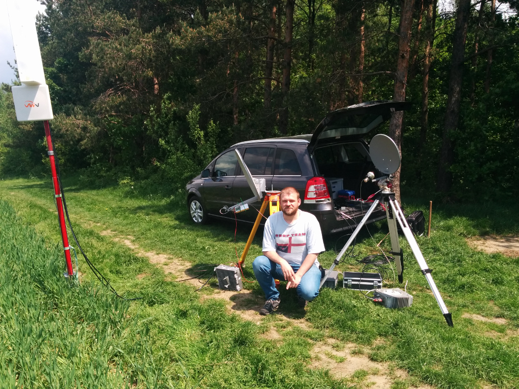
Just before the May DUR competition i got my new 6cm Transverter working. Before I faced some problems with the multiplier chain.
Murphy made that saturday afternoon i burned the control circuitry of the SMA bistable relay – poff. So i had to exchange it with my own sequencer circuitry that needs some highside FET switch to do that job.
I used a dual-band ring feed i made for tests and connected it to a old 60cm dish. The result you can see on the photo below. Very beta version ;) The PA is still missing and therefore i had only about 250mW.
I also wanted to take 3cm with me. In order to limit the amount of equipment i decided to minimize effort for 23cm. 13cm is out of order at the moment anyway. That means only using the former Wimax patch antenna for 9cm.
The following result i can claim:
23cm 12QSO 772P
13cm —
9cm 4QSO 481P
6cm 2QSO 351P (x2)
3cm 4QSO 489P
Sum 2444P
Next steps for 6cm will be adding driver (ordered from China) and the PA (10W, already here) as well as creating some better feed suitable for the mesh dish.
My goal is to operate 23/13/9/6 with one mesh dish.
This time i had a neighbour in JO61XA. DM4SWL was operating few meters away on 23cm FM only. Thanks for taking the foto !
6cm rig
after May 2017 DUR test
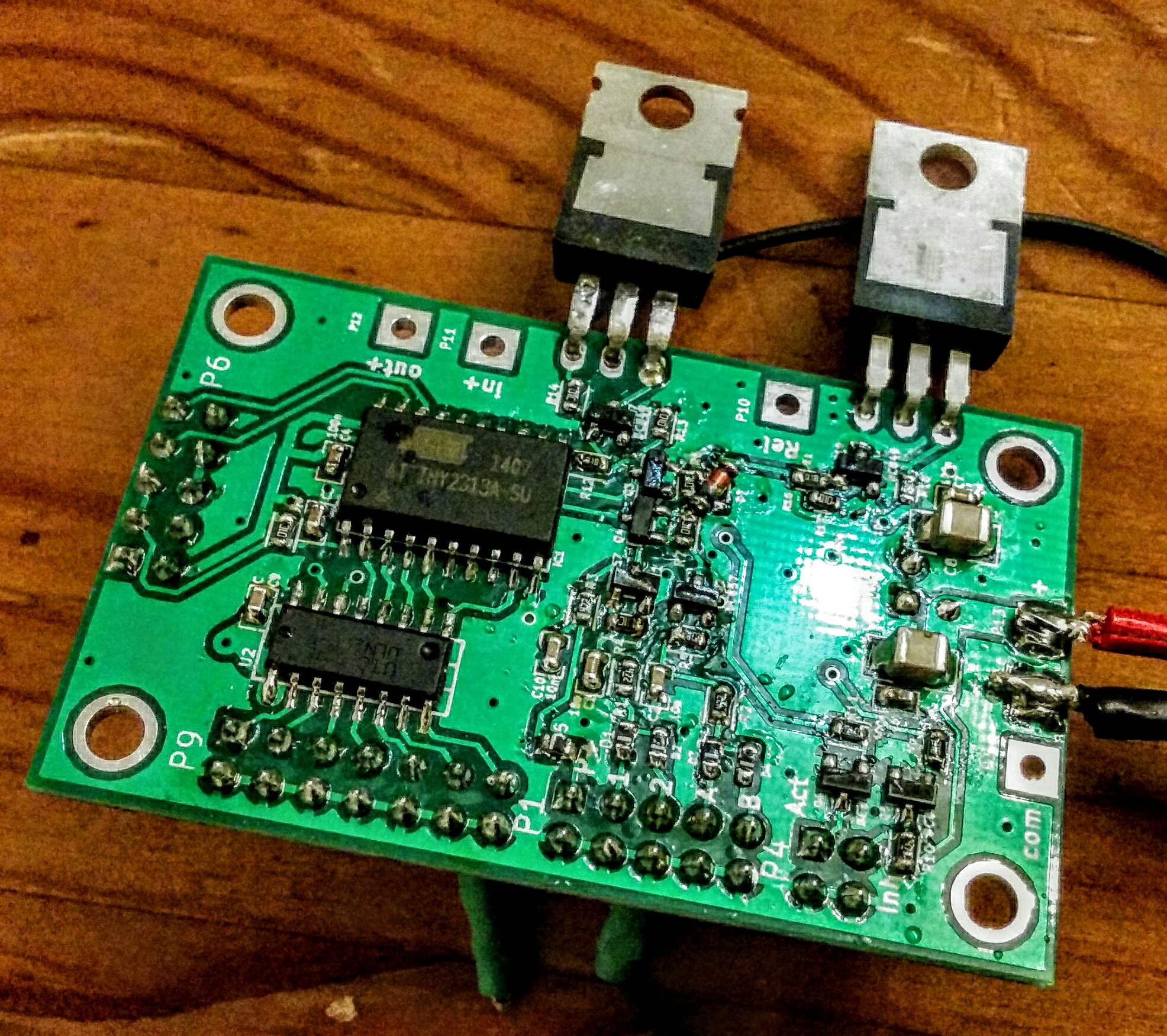
Attiny2313 + Uln2003 + highside FET switch for PA + lowside FET switch for RX-TX relais and a few bipolar Low Power stages on a two-layer board. The PTT input can be either high-side or low-side active. It also has lock input to connect several transverter to one antenna system. Via the driver IC a pulse relais and a fan can be controlled. There is also a Tx inhibit output that can be used with Yaesu tranceivers.
Schematic:
Attiny Sequencer Rev2 schematic
The circuit has two PTT inputs and two Error inputs (decoupled by diodes). A active high PTT input is available as well. There is a highside FET switch that can be used to drive a PA and a lowside FET switch that can be used for an RX/TX relais. The TX inhibit signal is available to drive the inhibit input of Yaesu transceivers. The active out is used to signal a sequencer in TX mode. This can be used to lock other sequencers via the error input. The ULN2003 driver is currently configured for another RX/TX relais, a fan which is running until 30s after releasing the PTT, another low active signal parallel to TX-inhibit (as PTT for TRX without TX inhibit) and output signals for a pulse relais (bi-stable RF relais). The serial interface (also used for ISP) is unused in the application. It might be possible to connect a temperature sensor for example.
The missing connection from Q4 to R7 is a print error.
The design was done with KiCad which is a open source PCB layout system. The code for the microcontroller was written in C. The 2k program memory are almost full now but one might be able to optimize. If you are interested in the design data let me know. I also have some spare PCB left over.
I wonder what else could be implemented with this PCB with the small program memory size. Feel free to give some ideas.
something for kids …
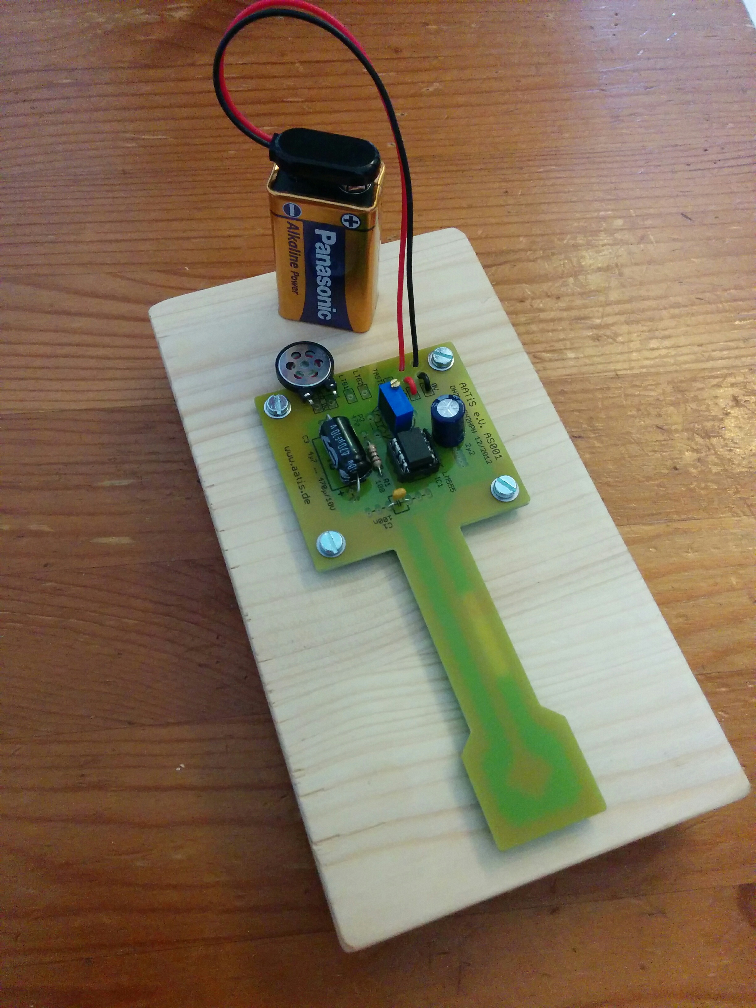
AATIS AS001 key
2nd version of the PCB i designed over 2 years ago. Hopefully without bad errors i hope ;) Lets see when the shipment will arrive…
I corrected the package of the microcontroller and swapped a few signal pins in order to gain some flexibility with the software.
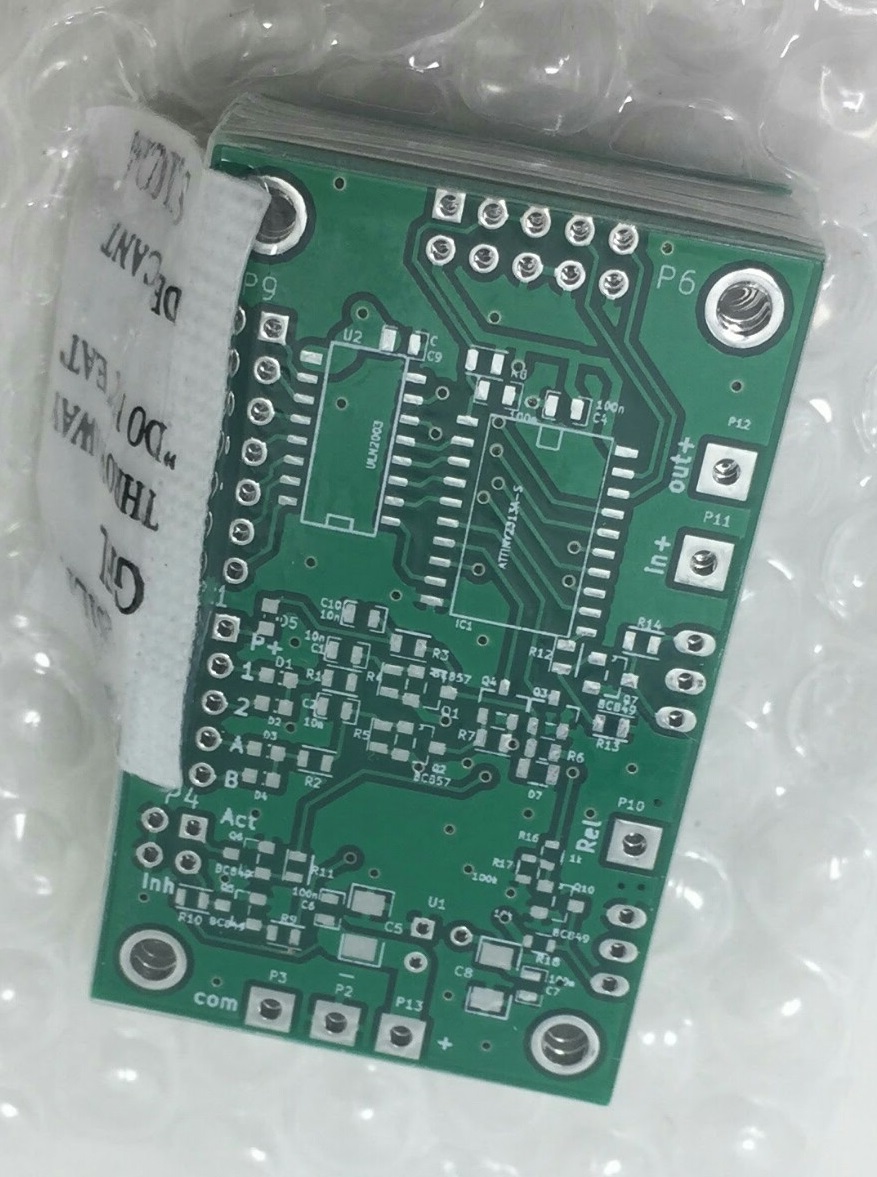
Sequencer version 2 PCB
Currently i assemble a 6cm transverter kit that was already in the shelf for quite some time. The PCB is mounted to the enclosure now and the filter cups are soldered as well.
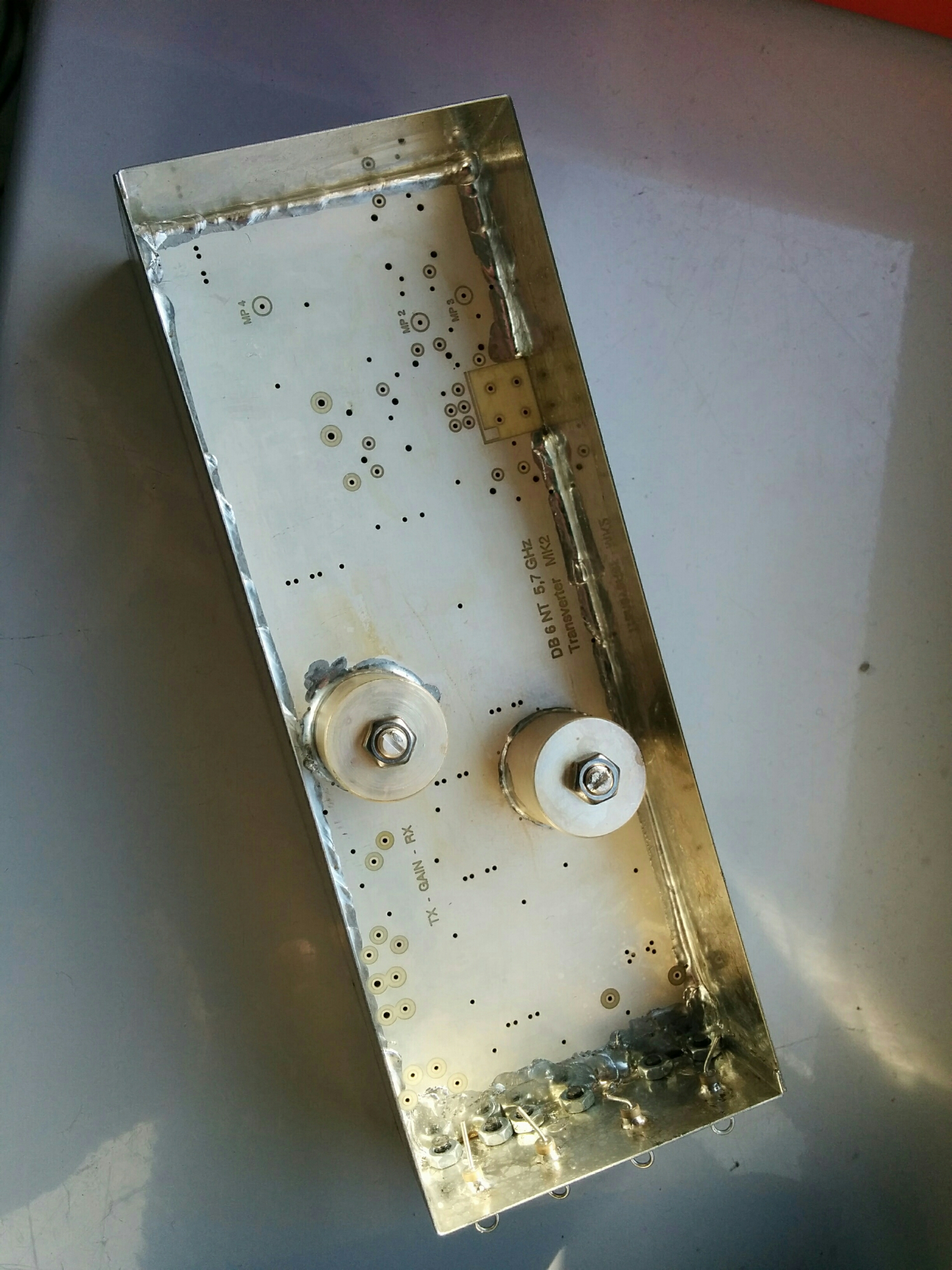
6cm transverter kit