VHF Yagi measurements

For our club events we had to reconstruct some old DK7ZB design yagies because too many of the 6mm diameter elements got broken over the years. We decided to modify the design for 8mm elements to get some more material for the screwholes.

All measurements were done with the VNWA2 with calibration point at the end of a 20m Ecoflex10 cable (directly at dipole connector).

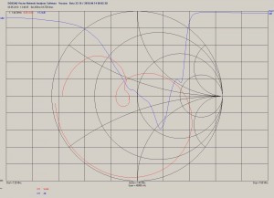
The measurement of the old construction in a high of about 4.5m looked like that:

8el_28Ohm_DK7ZB_6mm

8el_28Ohm_DK7ZB_6mm Elements

It can be clearly seen that there is something wrong. Maybe the reason is that some of the elements are going to break and some of them have been already repaired. I do not have a comparison to a version with new elements unfortunately.

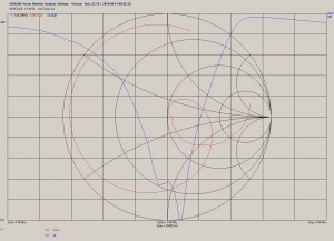
After modification to 8mm Elements and optimization of all element lengths with YO with keeping the element locations the picture looks like that:

8el_28Ohm_DK7ZB_8mm

8el_28Ohm_DK7ZB_8mm Elements

It can be seen that the best matching of the antenna is slightly too low which is not optimum with some ice on the elements during the march contest. But in general the matching looks like it should now.

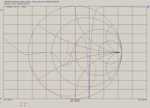
For comparison i measured my old 11ele Tonna Yagi as well. The picture surprised me.

Tonna_2m_11el

Tonna_2m_11el

The middle of the matching band is around 145MHz which should also do with some minor ice at the elements. The matching itself looks really good. Of course this does not tell anything about how well the antenna works ;)

FT-817 TX spectrum

Some months ago i purchased a defect Yaesu FT-817 radio. It turned out that PA and driver were defect. I was able to buy the PA transistors (RD07MVS1) and driver transistors (RD01MUS1) at DL2JWL (thanks!). I got some really good help in the 817-onair forum.
After the TX was operational i was interested in the output spectrum.
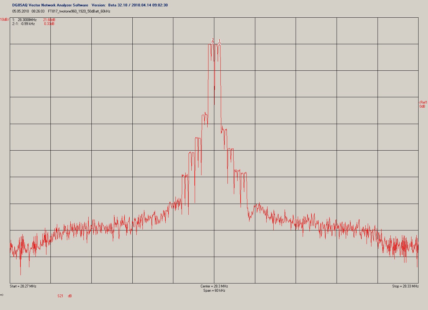
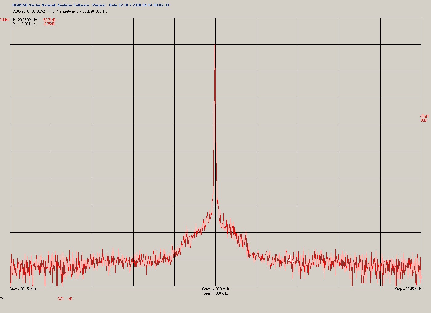
I did a singletone measurement (mode CW, 500mW) and a twotone measurement (mode DIG, 500mW, twotone signal from soundcard). Find the pictures below. The spectrum was measured with the DG8SAQ VNWA in spectrum analyser mode at 28MHz.
Please note that the RBW was 750Hz and you may want to recalculate noise levels.
One word about the twotone spectrum: The VNWA uses rectangular filters. Therefor the discrete tones apear to be rectangular spectrum. The gap inside each of the tones comes from the AC coupling of the measurement system which causes a notch at zero beat frequency.
The measurement results appear to correspond with spectral measurements by some OM in the US done some years before and measurements done by DF9IC. In fact the TX signal is not usable for a real contest because the sideband noise is around -80dBc within a bandwith of 3kHz.

FT-817 twotone spectrum 28MHz

FT-817 twotone spectrum 28MHz (750Hz RBW!)

FT-817 singletone spectrum 28MHz (750Hz RBW !)

FT-817 singletone spectrum 28MHz (750Hz RBW !)