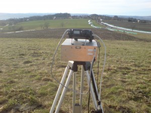
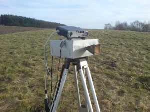
Last weekend i did some few daylight laser experiments during the V/U/SHF contest. Unfortunately the contact to Marcel, DK5WMA was not possible due to much fog on Saturday evening. Our receivers are still not capable to deal with daylight. But we work on that.
Category Archives: Amateur Radio
First DUR in 2011
The first DUR activity contest this year. DL4DTU borrowed his spare 24GHz transverter to me. DG2DWL convinced me also to take 23cm with me. I was not very active in calling CQ on 23cm, just worked the stations that i heard.
The rest of the time i used to try some QSO on 24GHz. For the contact to DH1DM and DG2DWL i had to move up the hill a bit.
The wheather was really nice and the conditions appeared to be better than usual.
A short video that shows the Elbsandsteingebirge on Sunday morning:
Receiving the 24GHz beacon DB0TUD at Triebenberg JO61XA:
Hope to hear you next time !
Another video of Quisk and N2ADR-TRX
I took another video that shows the capabilities of a wideband software defined radio frontend:
N2ADR transceiver live
Some live reception with the N2ADR transceiver frontend.
N2ADR software defined transceiver
Months ago i heard a talk of Andreas DL5CN about his software defined radio activities. He mentioned a hardware brought up by James N2ADR that works with his Linux SDR software QUISK. In the next both issues of the Funkamateur Guenter DL7LA and Detlef DL7IY described their experiences with the design.
The transceiver is a RF-to-bits design which means that the RF domain is samples with 122MSamples/s and bandfiltered, downconverted within an FPGA and transferred to the PC via an Ethernet interface. The transmit path is the other way around using a D/A converter. The details can be found in their article.
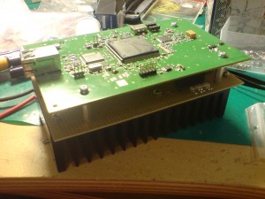
From them i got a commercial 2-layer PCB board with some improvements against the original layout from James. With the information i got from Guenter and Detlef and the info that can be found at James website i started purchasing the parts. It turned out that it is important to notice every piece of information very exact. In addition the power supply for the PCB is not part of the circuit (at least most of it). Therefore much effort needs to be spend to create a proper supply that also takes into account avoiding much noise in the supply for the analog parts of the circuit and avoid too much power dissipation in the regulators.
Last days i completed my power supply which now produces several voltages. 5V digital that supplies the regulators for 3.3V digital 2.5V digital for the FPGA. (An additional 1.2V regulator for the FPGA is located at the transceiver PCB and supplied by the 3.3V). At the analog side there are a 5V regulator for the RX preamp, 3.3V for the A/D, D/A converters and 7.5V for the MMIC TX amplifier. After some debugging i was able to load the FPGA configuration into the configuration flash. Today i was able to receive the first (self generated) signal with the receiver part.
Maximum RF bandwith can be between 25kHz and 500kHz.
There is still much todo. The circuit does still not contain any receiver preselection and no transmit amplifier except the few hundred mW that come out of the MMIC.
A funny thing was that nobody ever showed a picture of the bottom side of the PCB which is more or less a spiders web ;)
You can find further information and some more pictures at the Yahoo group i created for discussions. It can be found at
http://groups.yahoo.com/group/n2adr-sdr/
Multiplier Chain for 70cm -> 10GHz conversion
One of my long time projects is a transverter system for 10GHz build up with separate units.
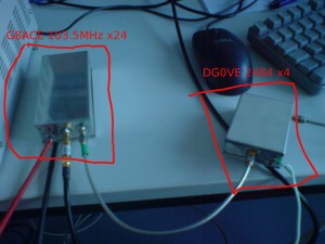
A while ago i purchased a multiplier unit for 2.5GHz input x4. Nowadays i purchased also a kit for a x24 multiplier from G8ACE.
With the G8ACE multiplier i am able to get an output of around 13dBm at 2484MHz with 0dBm drive at 103.5MHz.
This signal is directly used to drive the DG0VE multiplier which gives around 23dBm at 9936MHz. I mounted an additional SAW filter that came from an wireless LAN application between the last multiplier stage and the stripline filter of the G8ACE multiplier. This reduces the spurious signals that are far away from the wanted signal.
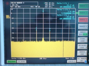
As you can see at the screenshot at 9936MHz there are still some unwanted spurious signals that seem to be caused by mixing effects.
DM7A team in october UHF/SHF contest – a short video
Last week i collected all the video snippets i took during our contest activity in october 2010.
I used the Linux Opensource video software Openshot. Music comes from the band Phonotrash.
Have fun with the video…
Output ripple on dm330mve
In my last post i described that my FT-817 is somehow sensitive to output ripple of switched power supplies.
My problems were caused when using it together with my Alinco DM330 30Amps supply.
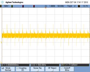
So i tried to have a look to it with an digital oscilloscope.
It has to be said that this picture was taken without any load at the supplies output. My feeling is that these spikes are quite high with around 150mVpp. Within the FT-817 this seems not to be filtered much and causes spurious spectral lines with the distance of the supplies switching frequency.
Whe i opened the supply afterwards i somehow dissapointed. The soldering points are really bad and seem to almost disappear at some parts. This makes me doubt that all the parts are correctly soldered. Maybe thats the reason for the ripple. This has to be investigated. I will not use the supply until that is clear.
Also you have to be carefull with the 100V/230V input voltage range switch. Do NOT switch it to 100V for accident.
FT-817 synthesizer problems ?
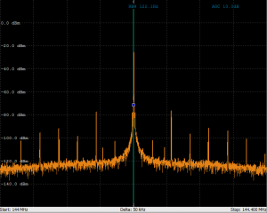
Today i had a look to the output spectrum of my FT-817 i use for 23cm operations. I looked to the IF signal of 144MHz.
There are several spurs with a distance of around 28.5kHz of each other and <50dB of the wanted signal. This corresponds to my observation that strong neighbour stations can be heard in regular steps again and again. It happens in CW and also in SSB mode. Does anyone have a idea what could be the cause ?
I assume the problem is somewhere in the synthesizer...
Update 2010/10/01
When looking to older screenshots i saw that they were not that spurious. The difference was, that i did not use the switched power supply from Alinco at that time but a linear one. So i checked again with a linear supply today. Result: Most of the spurs disappeared. Just some weaker ones are remaining.
DUR test september 2010
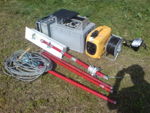
Last weekend: Another times DUR activity. Another time from Triebenberg JO61XA. This time i used my new power generator. Unfortunately i missed some extra fuel and so i had to go qrt a bit earlier.
Highlight was a qso to DR3M north of Hamburg.
Etwas noch: Wenn man sich ueber die Signalqualitaet eines anderen OM beschwert, dann bitte qualifiziert. Denn nur dann kann man auch tatsaechlich etwas unternehmen. Ein “Scheiss Signal.” ohne weitere Information hilft vor Ort wirklich nicht weiter.

