CQ WW DX CW November 2011

Some impressions from the 2011 CQ WW DX contest in CW. I did only make a few qso but the screenshots are impressive.

CW WW DX CW 10m - 1430UTC, Nov 26th 2011


CQ WW DX CW 20m

CQ WW DX CW 20m (Sunday)


CQ WW DX CW 40m (Sunday evening)

CQ WW DX CW 40m (Sunday evening)


CQ WW DX CW 80m (Sunday)

CQ WW DX CW 80m (Sunday)


CQ WW DX CW 160m (Sunday)

CQ WW DX CW 160m (Sunday)


As antenna i used my portable 10m vertical wire. Receiver was the N2ADR/HiQSDR frontend.

DRM reception with N2ADR frontend

The following video shows a reception test of a shortwave DRM station using the direct sampling frontend designed by N2ADR. The SDR software Quisk allows for adjustable filter bandwidth up to 21kHz from version 3.5.2.
The soundcard output was fed into another PC’s soundcard. There DREAM DRM software decoder was running.

DRM reception with N2ADR frontend and Quisk 3.5.2 and DREAM

N2ADR frontend TX measurements

After bringing up the transmitter section of my N2ADR frontend i measured some IMD and spectral purity data.
Quisk has a nice feature to create very clean measurement tones internally. This makes measurements very easy.
The amplifier after the TX DAC is a BGA6589 supplied with 80mA out of a 7.5V source.
When not driving the DAC with full power i see really good IMD figures. IMD3 around -45dB below the wanted signal.
With full drive the IMD3 decreases to around -20dB. (The figures were taken with 20dB attenuator between frontend and measurement receiver!)

IMD -6dB at 28MHz

N2ADR frontend IMD test with -6dB output at 28MHz


When looking to lower frequencies (lets say below 10MHz) and transmission of a sine carrier the spectral purity looks rather good. The next figure shows a 40M signal which gets around -110dB noise 100Hz off the transmission frequency.
7MHz carrier close

looking close to a 7MHz sine carrier


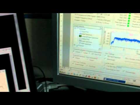
At the upper edge of the frequency range of the frontend the situation becomes significantly worse. The internal digital oscillator seems to create many spurs over a wide frequency range.
55MHz sin spectrum

spectrum of a 55MHz sine carrier


55MHz sine wide

wideband spectrum of 55MHz sine carrier


For low output frequencies the wideband spectrum looks rather promising except for the overtones. But the TX signal was completely unfiltered after the DAC. So proper lowpass filters for every band will be necessary anyway. Probably also the input of the MMIC was a bit overdriven. I did not check this so far.
80m overtones

80m Band sine carrier and overtones


Looking to the spectrum that would fall inside the amateur band during real world operation another effect appeared. Independant which frequency is used there are symmetric spurs left and right of the TX spectrum. Two at +-52kHz and two (with more noise) at +-61kHz. Currently it is not clear if these come from internal circuits of from the power supply. Probably both ?
3.6MHz sine carrier close by spurs

3.6MHz sine carrier close by spurs


Overall the performance is already rather good. Especially at the top end of the frequency range there is range for improvement which is necessary to make the frontend a good choice for usage with transverters for VHF/UHF contest operation.

N2ADR software defined transceiver

Months ago i heard a talk of Andreas DL5CN about his software defined radio activities. He mentioned a hardware brought up by James N2ADR that works with his Linux SDR software QUISK. In the next both issues of the Funkamateur Guenter DL7LA and Detlef DL7IY described their experiences with the design.
The transceiver is a RF-to-bits design which means that the RF domain is samples with 122MSamples/s and bandfiltered, downconverted within an FPGA and transferred to the PC via an Ethernet interface. The transmit path is the other way around using a D/A converter. The details can be found in their article.
From them i got a commercial 2-layer PCB board with some improvements against the original layout from James. With the information i got from Guenter and Detlef and the info that can be found at James website i started purchasing the parts. It turned out that it is important to notice every piece of information very exact. In addition the power supply for the PCB is not part of the circuit (at least most of it). Therefore much effort needs to be spend to create a proper supply that also takes into account avoiding much noise in the supply for the analog parts of the circuit and avoid too much power dissipation in the regulators.
Last days i completed my power supply which now produces several voltages. 5V digital that supplies the regulators for 3.3V digital 2.5V digital for the FPGA. (An additional 1.2V regulator for the FPGA is located at the transceiver PCB and supplied by the 3.3V). At the analog side there are a 5V regulator for the RX preamp, 3.3V for the A/D, D/A converters and 7.5V for the MMIC TX amplifier. After some debugging i was able to load the FPGA configuration into the configuration flash. Today i was able to receive the first (self generated) signal with the receiver part.
Maximum RF bandwith can be between 25kHz and 500kHz.
There is still much todo. The circuit does still not contain any receiver preselection and no transmit amplifier except the few hundred mW that come out of the MMIC.
A funny thing was that nobody ever showed a picture of the bottom side of the PCB which is more or less a spiders web ;)
You can find further information and some more pictures at the Yahoo group i created for discussions. It can be found at
http://groups.yahoo.com/group/n2adr-sdr/

N2ADR SDR transceiver

N2ADR SDR transceiver PCB and power supply

Multiplier Chain for 70cm -> 10GHz conversion

One of my long time projects is a transverter system for 10GHz build up with separate units.
A while ago i purchased a multiplier unit for 2.5GHz input x4. Nowadays i purchased also a kit for a x24 multiplier from G8ACE.
With the G8ACE multiplier i am able to get an output of around 13dBm at 2484MHz with 0dBm drive at 103.5MHz.
This signal is directly used to drive the DG0VE multiplier which gives around 23dBm at 9936MHz. I mounted an additional SAW filter that came from an wireless LAN application between the last multiplier stage and the stripline filter of the G8ACE multiplier. This reduces the spurious signals that are far away from the wanted signal.
As you can see at the screenshot at 9936MHz there are still some unwanted spurious signals that seem to be caused by mixing effects.

Multiplier chain for 10GHz transverter project


Output spectrum of the chain with 103.5MHz input at 0dBm

FT-817 synthesizer problems ?

Today i had a look to the output spectrum of my FT-817 i use for 23cm operations. I looked to the IF signal of 144MHz.
There are several spurs with a distance of around 28.5kHz of each other and <50dB of the wanted signal. This corresponds to my observation that strong neighbour stations can be heard in regular steps again and again. It happens in CW and also in SSB mode. Does anyone have a idea what could be the cause ? I assume the problem is somewhere in the synthesizer... Update 2010/10/01
When looking to older screenshots i saw that they were not that spurious. The difference was, that i did not use the switched power supply from Alinco at that time but a linear one. So i checked again with a linear supply today. Result: Most of the spurs disappeared. Just some weaker ones are remaining.

FT-817 CW constant tone, 5W, span 400kHz

Recycling old CB radios

Some weeks ago i found an interesting webpage. At funkservice.at Gerhard offers PLL modules and DDS modules that fit to the LC7132 pinout of old CB radios. With these modules you can change your old 40 channel CB radio into an 80 channel version. I did this with my old dnt Carat exclusiv which was one of my very first radios that i ever owned. Now it has full 80 channels.
Unfortunately with this modification it lost its operating permission :)
But i am writing these lines because Gerhard also offers modules to modify old CB radios for FM usage within the 10m amateur band FM range. The modules will do automatic repeater shift within the 10m repeater frequencies.
This might be a good way to get some activity to this band using old CB rigs for doing some local qso on 10m in FM.
It is also a chance to support newcomers with transceivers that cost just a few Euro.

dnt Carat converted to 80ch

dnt Carat converted to 80ch

D-Star under impulse noise conditions

Last week DL3OCK generated a testfile for me. This file contains an FM signal and an D-Star signal with 50kHz offset. It can be transmitted with special equipment. I used this to check the behavior of my C5 70cm transceiver close to noise level and with impulsive noise. Find the videos below.

http://www.youtube.com/v/0Zz1Qd5ch4A

This video shows the comparison between D-Star and FM at around -115dBm.
It is clearly audible that D-Star has some advantages against FM if the decoder can stay in sync. The microphone of the camera does not represent the FM very well. In reality the FM sound was slightly better.

http://www.youtube.com/v/0mD1gWB2B58

This video shows the performance of FM vs D-Star under impulsive noise conditions. It is clearly audible that D-Star works without problems when FM is hard to understand.