CAT control of FT-817

Last days i did some experiments controlling the FT817 via CAT. I implemented some basic commands in the math scripting environment Octave (which is a Matlab compatible software). The communication with the serial CAT interface is not possible directly because Octave does not support serial communication. Therefore i used the VSPE (virtual serial port emulator) to connect the serial port to a TCP port which can be addressed out of Octave.

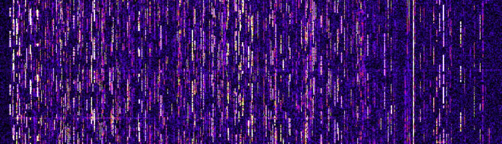
I wrote a script that can tune over a frequency range and reports the signalled S-meter output. In the end a diagramm of the S-meter output versus frequency is drawn. If you have a narrow filter (e.g. 300Hz CW) than you may use this to get somewhat like a “spectrumscope”. Compare the two pictures below which show a D-Star signal in 70cm band recorded with the FT817 and with  a R&S FSP spectrum analyser. It is clear that there is a low dynamic range and no information what the S-meter readings correspond to in terms of dB but it comes more or less for free.

Short guide: switch transceiver to desired modulation mode and filter bandwith, edit the frequencies and stepsize in the main scan script, start the VSPE software with correct settings, edit the ft817_connect.m script accordingly, start the scan script.

D-star spectrum measured with R&S FSP

D-star signal observed with FT817, 300Hz filter, CW mode

Find some scripts here: octave_ft817_cat_scripts

VHF Yagi measurements

For our club events we had to reconstruct some old DK7ZB design yagies because too many of the 6mm diameter elements got broken over the years. We decided to modify the design for 8mm elements to get some more material for the screwholes.

All measurements were done with the VNWA2 with calibration point at the end of a 20m Ecoflex10 cable (directly at dipole connector).

The measurement of the old construction in a high of about 4.5m looked like that:

8el_28Ohm_DK7ZB_6mm

8el_28Ohm_DK7ZB_6mm Elements

It can be clearly seen that there is something wrong. Maybe the reason is that some of the elements are going to break and some of them have been already repaired. I do not have a comparison to a version with new elements unfortunately.

After modification to 8mm Elements and optimization of all element lengths with YO with keeping the element locations the picture looks like that:

8el_28Ohm_DK7ZB_8mm

8el_28Ohm_DK7ZB_8mm Elements

It can be seen that the best matching of the antenna is slightly too low which is not optimum with some ice on the elements during the march contest. But in general the matching looks like it should now.

For comparison i measured my old 11ele Tonna Yagi as well. The picture surprised me.

Tonna_2m_11el

Tonna_2m_11el

The middle of the matching band is around 145MHz which should also do with some minor ice at the elements. The matching itself looks really good. Of course this does not tell anything about how well the antenna works ;)

FT-817 TX spectrum

Some months ago i purchased a defect Yaesu FT-817 radio. It turned out that PA and driver were defect. I was able to buy the PA transistors (RD07MVS1) and driver transistors (RD01MUS1) at DL2JWL (thanks!). I got some really good help in the 817-onair forum.
After the TX was operational i was interested in the output spectrum.
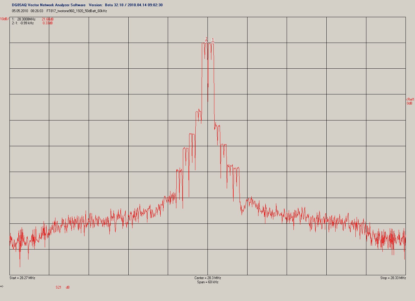
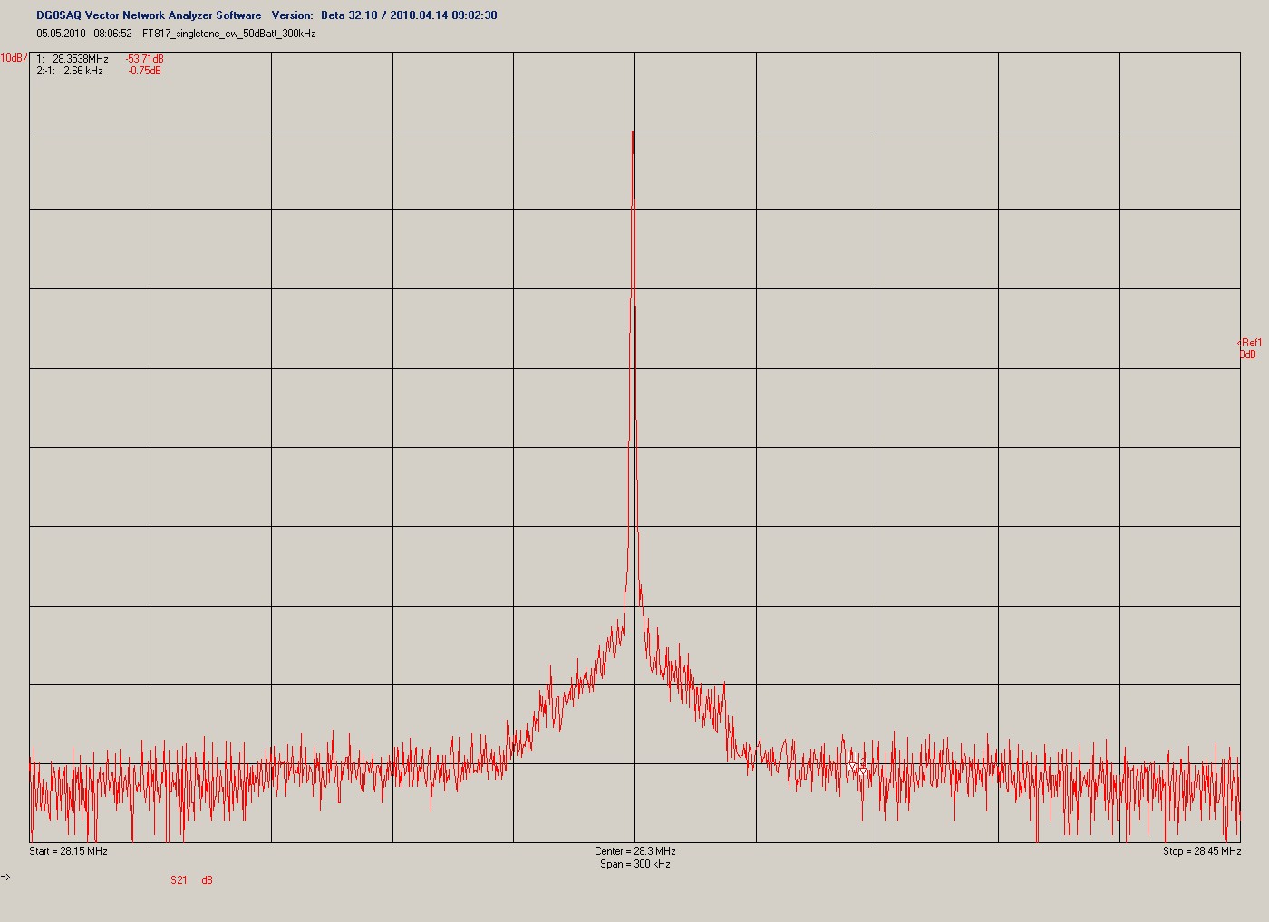
I did a singletone measurement (mode CW, 500mW) and a twotone measurement (mode DIG, 500mW, twotone signal from soundcard). Find the pictures below. The spectrum was measured with the DG8SAQ VNWA in spectrum analyser mode at 28MHz.
Please note that the RBW was 750Hz and you may want to recalculate noise levels.
One word about the twotone spectrum: The VNWA uses rectangular filters. Therefor the discrete tones apear to be rectangular spectrum. The gap inside each of the tones comes from the AC coupling of the measurement system which causes a notch at zero beat frequency.
The measurement results appear to correspond with spectral measurements by some OM in the US done some years before and measurements done by DF9IC. In fact the TX signal is not usable for a real contest because the sideband noise is around -80dBc within a bandwith of 3kHz.
FT-817 twotone spectrum 28MHz

FT-817 twotone spectrum 28MHz (750Hz RBW!)
FT-817 singletone spectrum 28MHz (750Hz RBW !)
FT-817 singletone spectrum 28MHz (750Hz RBW !)

DUR Contest April 2010

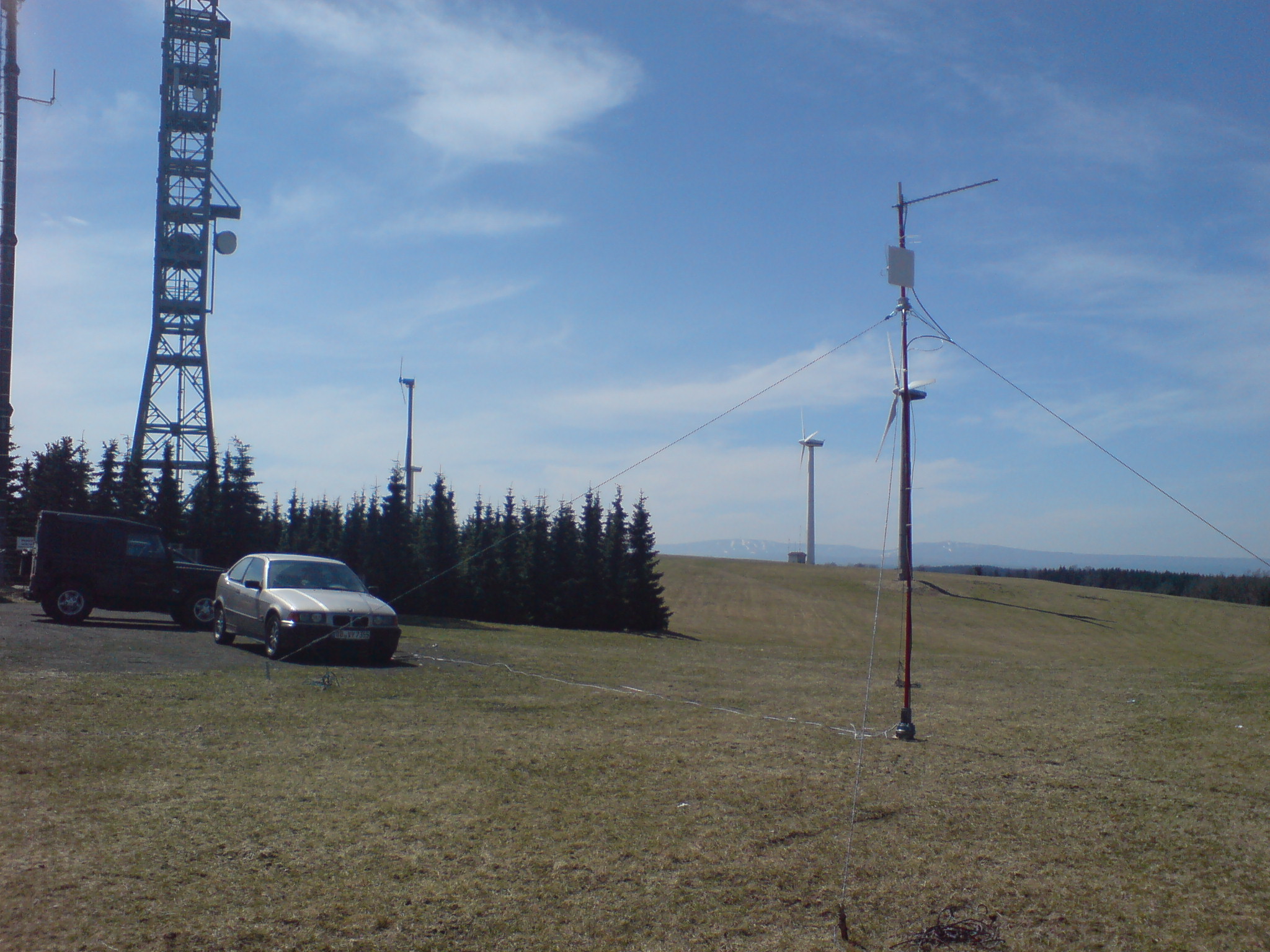
This was my first DUR activity this year. I found time to participate from Hirtstein/JO60OM. DL2LCE and DL8WQQ were there as well and operated some hundred meters away. This was the first time i tried my FT-817 together with the transverter and a new LNA stage as well. Surprisingly heard no beacons before the contest started. But a test with DG0VOG showed that all things were working properly, puuh. Unfortunately there were complaints about my signal by DL2LCE which i have to follow up now. So i did not call CQ on my own and just worked stations. In the end i had 18QSO and around 1200km in sum.
BTW. the small panel antenna is for 5GHz WLAN as it can be used for Hamnet.

DUR Apr10, JO60OM

AX25 with OpenWRT backfire 10.03

Today i tried OpenWRT backfire 10.03 with AX25. Last versions i had hard problems getting ax25 compiled for brcm47xx and also problems with the floting point emulation inside the kernel. First made usage of the native linux ax25 tools impossible and last prevented usage of the popular ax25 router software xnet (which is unfortunately closed source). Either one or the other worked.
Today first the AX25 stuff was not build as well when i selected kmod-ax25 inside “make menuconfig”. But after i selected the ax25 kernel support inside “make kernel_menuconfig” suddenly the kmod-ax25 module was build. That happened never before ;) I also switched on kernel FPU emulation which is off per default. And what should i say. Also XNET worked after i flashed all the stuff to the router. So OpenWRT backfire should be an excellent point to start AX25 operation with.

Repairing FT-817

Recently i bought a used FT-817 (non ND version). I knew that it had a damaged PA but i should have read about the FT-817 in common before buying it ;) The PA finals were totally dead as well as one of the drivers.
Therefore i bought new ones at DL2JWL and replaced them. Especially at the finals unit this is not very easy and it is suggested to replace the complete final unit for unexperienced users.
In addition it is necessary to change some other parts at the final PCB as well. Now the amplifier stage works well again. But there are still some steps to do. For example exchanging the rotary channel encoder which is hard to get and to do all the adjustments in the service menu. In the end i hope to get a nice transceiver for usage as transverter IF stage.