VHF contest from home

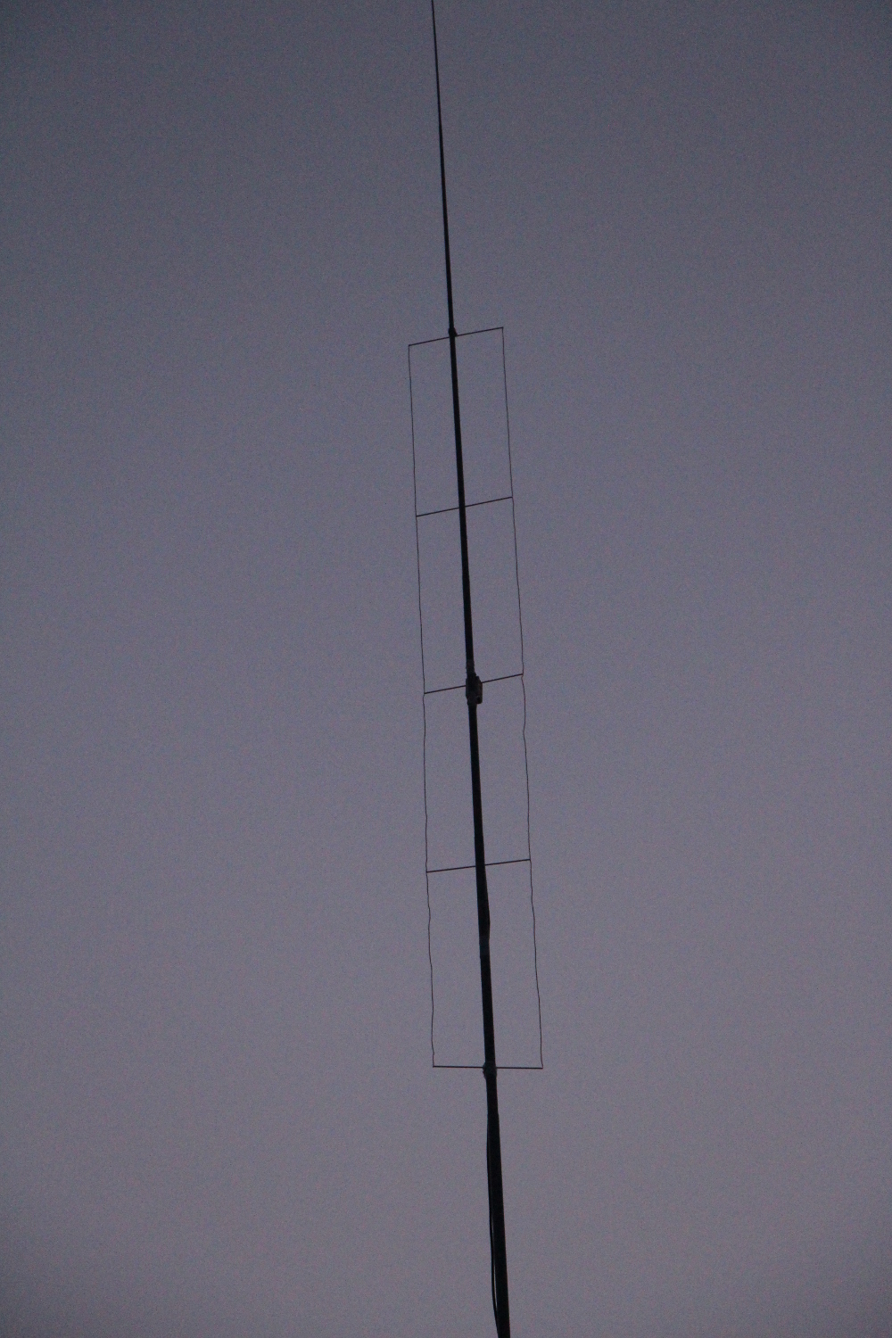
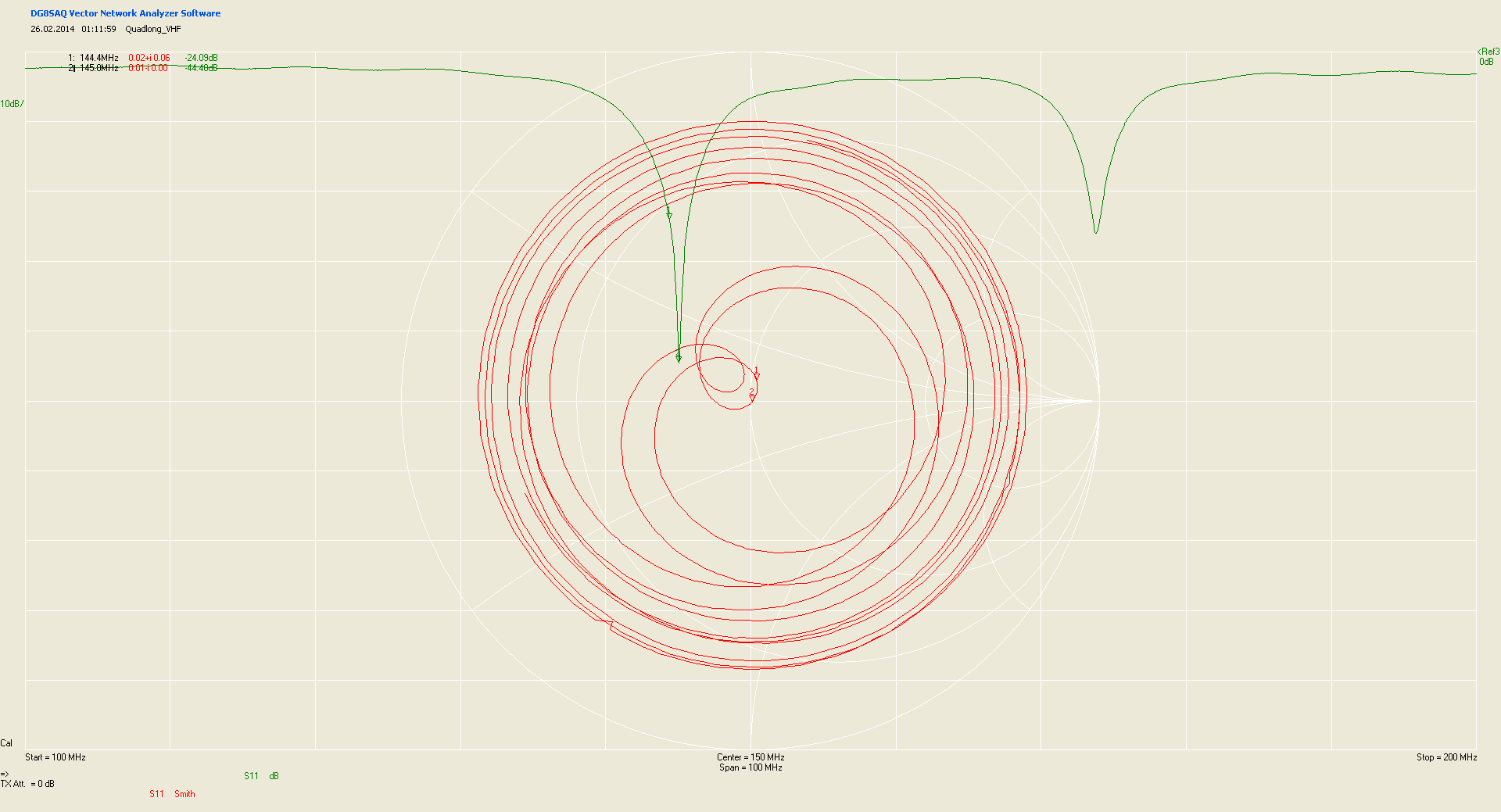
Due i was not able to join the DM7A activity from JO60LK this time i decided to try a few contacts from home in JO61VB. My location is in the Elbe valley at the eastern slope. I mounted a DK7ZB Quadlong antenna to my fibre mast installed to the balcony. Find some report on the antenna here: http://dh5ym.hopto.org/wiki/?p=1138
Only 50W were available from my FT-857D transceiver because the PA was in JO60LK serving as spare.
Surprisingly even with this tiny setup from a that bad location it was possible to make some DX contacts. I just operated about 4.5hours and got 57QSO with about 190km average.
In the map the directions of the Elbe valley are clearly visible. Especially direction of Poland i was not able to work anyone. I had the impression that relatively few stations were calling CQ. Maybe that was just related to my poor RX but possibly that trend continues to move from the microwave bands to VHF as well. Using ON4KST chat it was possible to arrange for some nice contacts in addition to a few random QSO.
ODX was PA1T with 535km. Others in top 5 are S59P, HA2U, DL0LN and OM3CPF.
Many thanks to all who had the patience to copy my qrp signal.

Sept 14 QSOs from JO61VB

Sept 2014: QSOs from JO61VB

DF9NP PLL / simple 10GHz test signal generator

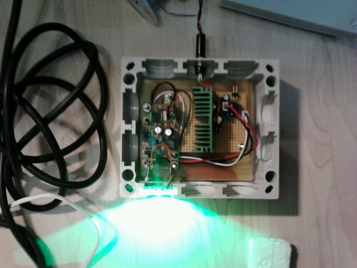
Dieter, DF9NP offers nice PCBs with VCOs locked to 10MHz precision TCXO. I ordered one with 0.28ppm TCXO and Dieter was so kind to tune one of the VCO to a frequency of 2592.2MHz. Together with a Multiplier x4 made by DG0VE this makes a nice generator that shows up around 10368.8MHz. I connected the both units to a small horn and placed it close to the window. The signal was visible on the websdr screen immediately. The oscillator from Dieter has about 14dBm output while the output buffer amplifier can be switched by connecting one pin to ground. The multiplier has about 200mW output at 10GHz.
During the first test i noticed that the airflow through the open window was changing the frequency of the TCXO slightly. This caused some instability at 10GHz. During a measurement in the lab i saw that the airconditioning was causing a even more significant drift while isolation from the surrounding air results in a very stable signal. Therefore i decided to put the oscillator in a metal can. This also improves the heat dissipation of the linear regulator for the PLL supply voltage.
The pictue shows the test setup close to my window.

10GHz test signal generator

10GHz test signal generator


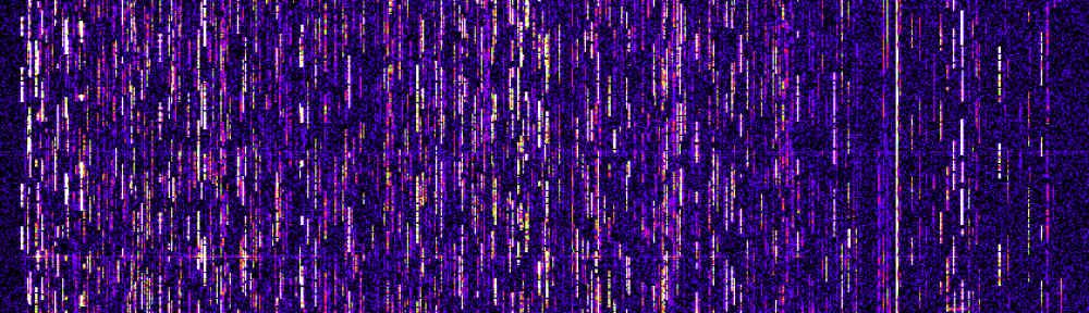
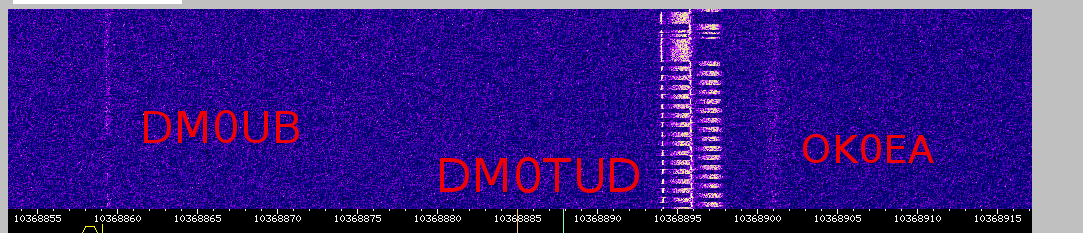
The screenshot from the Dresden 10GHz WebSDR shows the test signal at the lower end of the scale and the DM0TUD beacon at the upper end. The distance from my location to the WebSDR is about 7km and i have some houses and trees directly in the path.
10GHz testsignal on WebSDR

10GHz testsignal on WebSDR


test signal spectrum at 10GHz

test signal spectrum at 10GHz

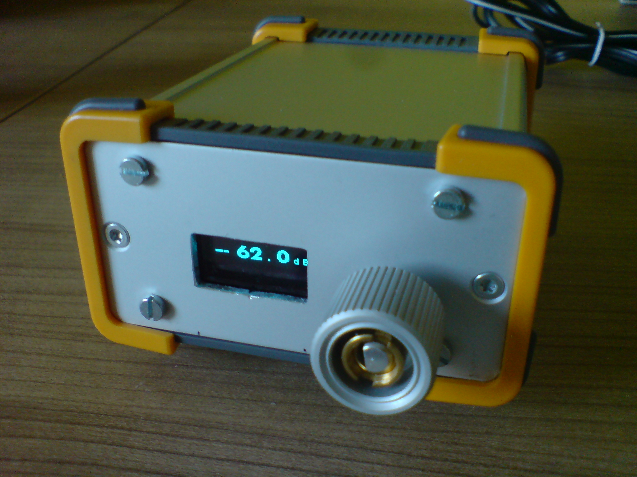
62dB step attenuator by SV1AFN

A nice page and a source of some good projects is the one of Makis, SV1AFN.
The page can be found at sv1afn.com.
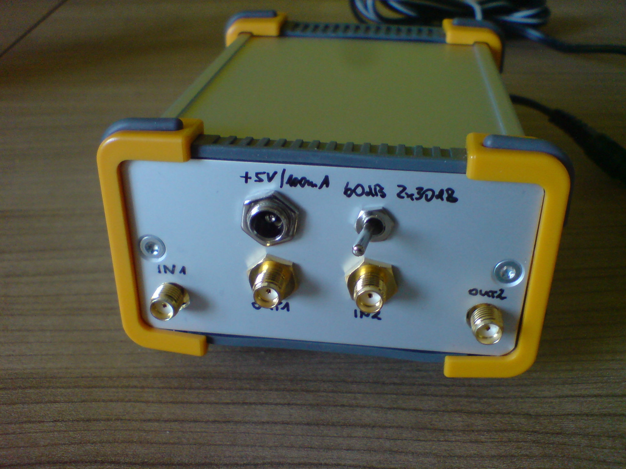
I purchased the step attenuator control module with 2x 32dB attenuator blocks. The both blocks can either be used in parallel always set to the same attenuation level or in series allowing a maximum attenuation range of about 62dB.
Build into a small enclosure it gives a really nice unit for your daily usage.

sv1afn step attenuator - front

sv1afn step attenuator – front

sv1afn step attenuator - rear

sv1afn step attenuator – rear

2014 May DUR Activity

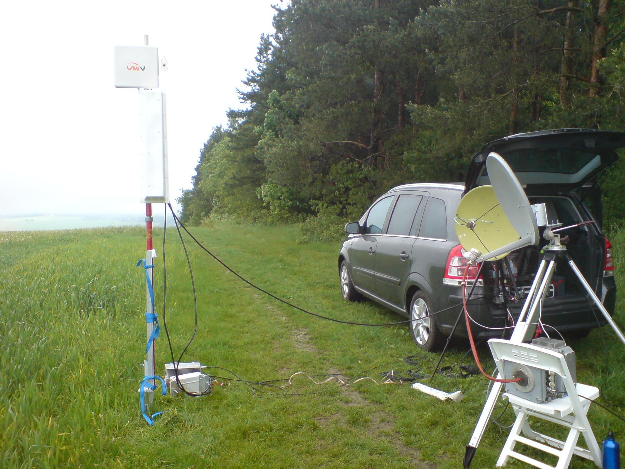
This time a completely different setup again.
23cm 15W with Quados, 13cm 1W with double quad element (i had nothing better, sri), 9cm 5W with Wimax-Patch antenna, 6cm with dish (the green one) borrowed from DL4DTU (TNX !), 10GHz/24GHz 5W/130mW with 6cm offset dish (transverters borrowed from DL4DTU).
This time Harald, DG3UH joined and we did a number of QSO on almost all bands. Only 24GHz did not work well with DL4DTU and there was no other station activa on that band.
If i remember correct: 23cm 9QSO, 13cm 5QSO, 9cm 1QSO, 6cm 3QSO, 3cm 1QSO, 1.2cm 0QSO.

DUR201405

DUR201405

10GHz Rainscatter on WebSDR

Last week i took a screenshot of some RS signal on the local 10GHz WebSDR (http://microwavesdr.hopto.org:8901).
The picture shows the signal of DM0TUD with some strong rainscatter reflection with some doppler offset and frequency spread.
The spread and the shift are caused by reflection at falling raindrops during some local rain.
The clouds where high enough to give also some reflections from the beacons DM0UB (Berlin) and OK0EA (Prague) which can be seen as lines in the waterfall display.
dm0tud_dm0ub_rs_s

DUR April 14

2014 04 DUR 23cm setup

2014 04 DUR 23cm setup

rotor control + hiqsdr

rotor control + hiqsdr

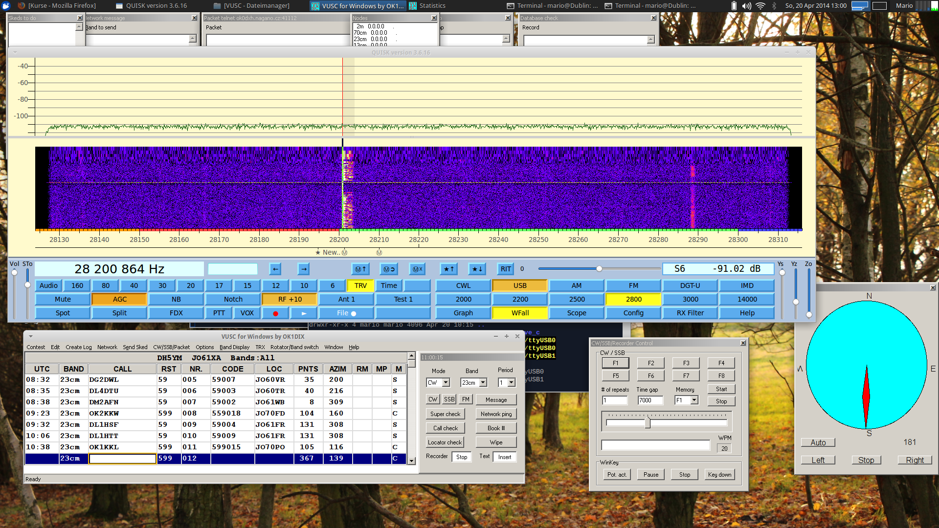
With hiqsdr, transverter and new rotator control on 23cm. Low activity but nice weather.

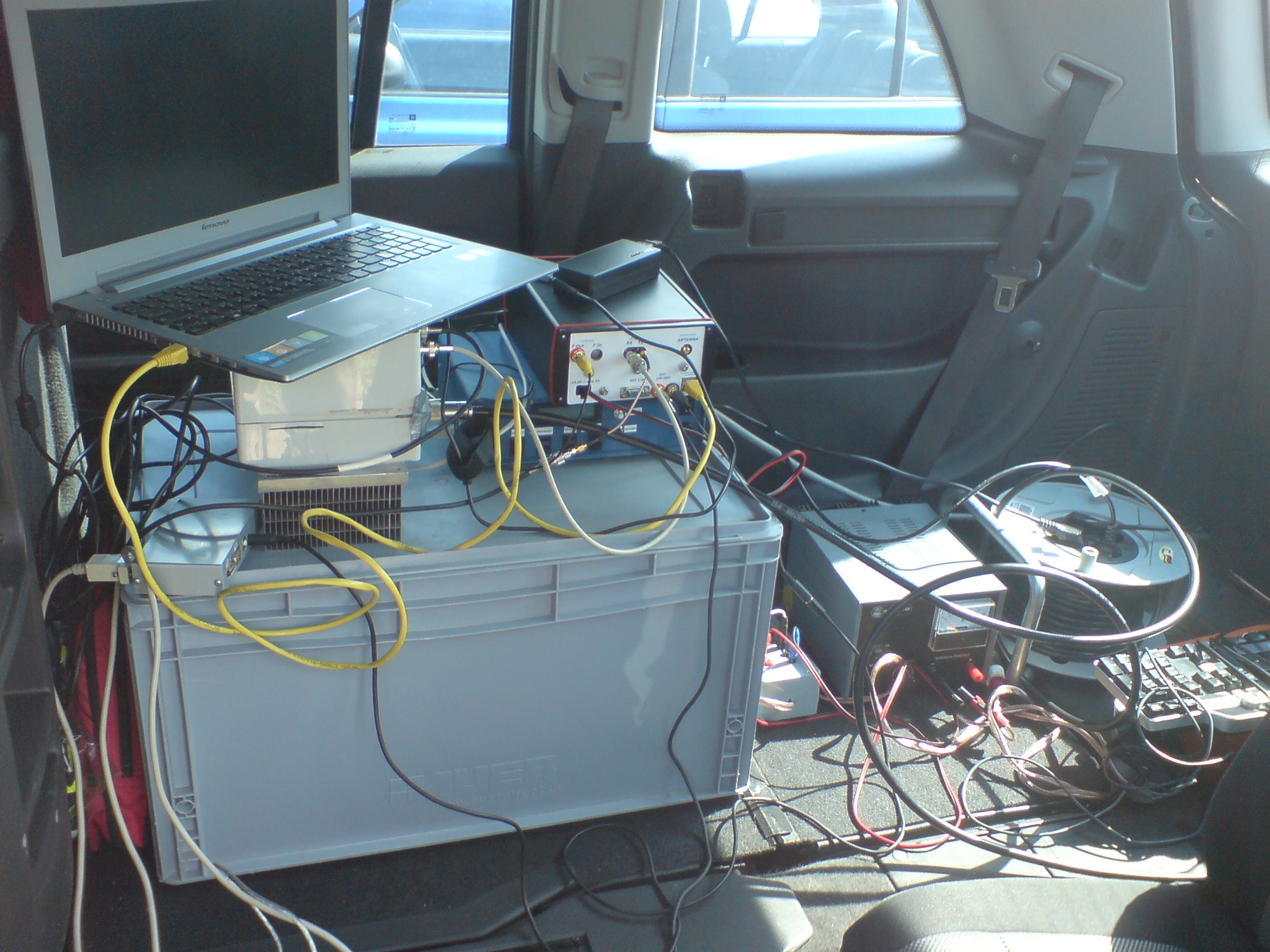
I decided to try some new setup. The recently completed rotator control was used with VUSC to turn the antenna to the destination automatically. I was first time using my HiQSDR setup portable with a 23cm-10m transverter borrowed from DL3JAN. Therefore i skipped 13cm/9cm.

The last picture shows a screenshot of the signal from DL1DXA at the end of the DUR test.

Screenshot DUR 04/14

Screenshot DUR 04/14

HiQSDR repaired…

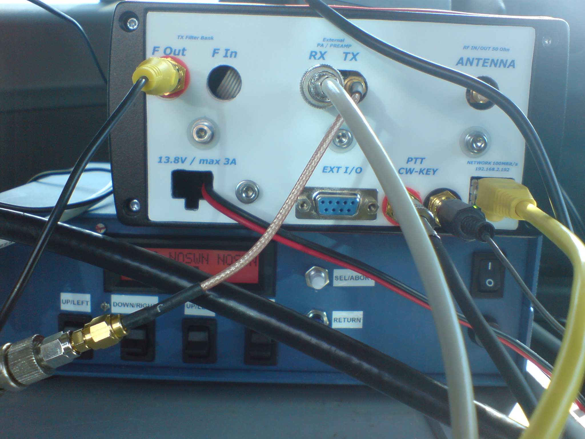
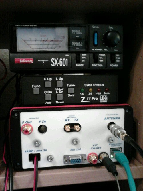
A while ago i destroyed the RX input amplifier of my HiQSDR. Last weekend i replaced the two hittide switches and the differential amplifier of that circuit. Now its fully operational again. On the photo you see the backside of the HiQSDR enclosure as well as my antenna tuner and the SWR/Power meter. The transceiver itself does not have any human interface. It just has inputs for power, RF, key and PTT and outputs for RF, PTT and some control signals.
The digital baseband goes via UDP connection to the SDR PC. Usually i use my Laptop connected via Wifi.
image

once again – DL1DBR rotator control

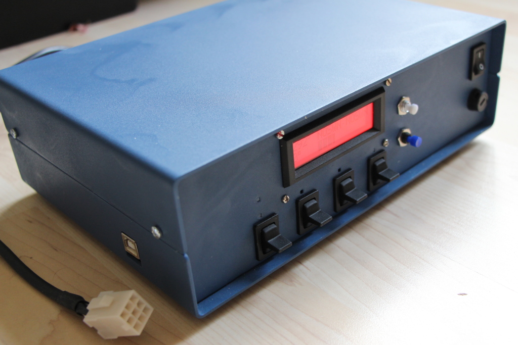
My rotator control unit (design by DL1DBR) is more or less finished now.
All the stuff is in the enclosure and working. Items that i needed to solve were:
– deal with some bug in the PCB print were the names for the connectors for Keys and LCD are mixed up ;)
– connecting the KR600 rotator which is 24V AC with end switches which needs two driver PCB in parallel to keep this function
– change the connection of the poti in the rotator unit to measurement voltage over the complete 500 Ohms
– change the software to allow for stopping the motor in the moment the direction key is released (before it stopped only on pressing the OK button)
– changing some libraries to get it compiling in my environment
– deal with the CDC UART (i replaced the CDC done with Attiny2313 by a FTDI UART-USB converter, this works in all environments in contrast to the CDC)
– search for a suitable 24V AC power supply for the motor
– get the DC for the controller working in the environment with the motor (i decided to spend a 2nd trafo for the logic because that was the fastest way to get rid of the interference which disturbed all the resistor measurements)
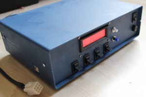
Rotor Control unit DL1DBR

Rotor Control unit DL1DBR


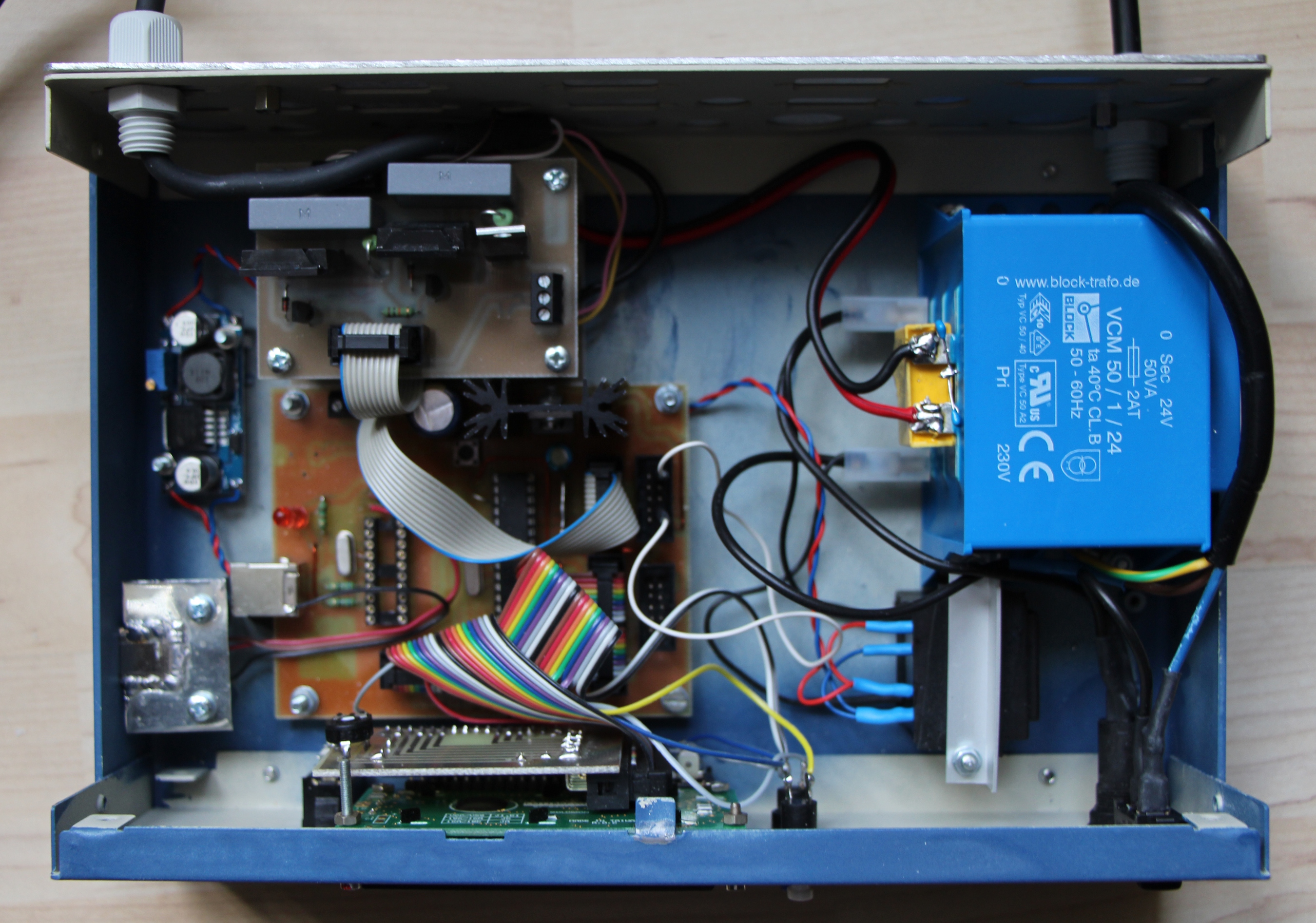
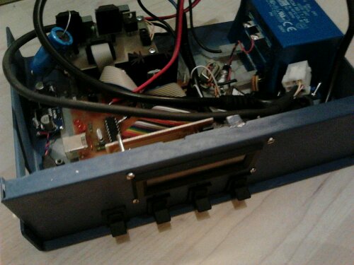
The following picture shows the inner of the rotator control unit.
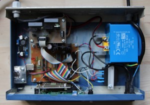
Inner of Rotator control unit

Inner of Rotator control unit


Starting with the right upper edge: Thats the 24V AC transformer that supplies the motor of the rotor unit. Below that there is a small black part. Thats the 15V transformer that generates the voltage for the digital part. Using the 24V from the motor supply resulted in crazy measurements due to the strong interference from the motor. At the lower edge you can see the display PCB mounted to the frontside of the enclosure together with the keys. Above there the brown PCB is the main control unit that is driven by a Atmega controller. It gets its supply from the blue PCB on the left edge of the enclosure which is a DC/DC converter that generates about 8.5V out of the voltage from the black transformer. The PCB above the controller PCB is the driver for the motor. Actually its two identical PCBs stacked. The capacitor for the phaseshift of the motor resides in between this stack. The PCBs use each two solid state relais for switching the supply voltage.
For the remote control of the unit i replaced the Attiny CDC implementation by a FTDI USB-UART adapter that is mounted at the left side. Its the silver part there.
In case you have questions… Let me know.