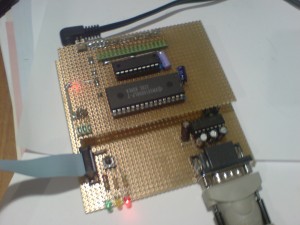
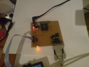
The Atmega8515 features a external memory interface that can be used to interface a external SRAM memory. The picture shows my Atmega8515 board with the
addon SRAM board. The small IC is a 74HC537 8-bit latch. The big one is a 128kByte SRAM memory. Only 64bit out of these can be addressed by the microcontroller. One thing that i found worth to notice is: The SRAM has two chip select inputs. The first is /CS1 and the second is CS2. The aim is to use one select signal (without inverter) to distinguish between two memories. I thought it is enougth to use one of the inputs and let the second floating. This was a mistake that caused me some hours of hunting a failure of sporadic instabilities during memory access. ;) The memory access is only valid if /CS1 is low and CS2 is high. I should read the datasheet before next time.
At the moment the whole application runs with a 12MHz crystal and without inserting wait-cycles during memory access. Hence i have a 74AC537 high speed latch i will try to go to 18.432MHz again. Above 14MHz it should be necessary to insert a wait cycle for read and write since the memory latency becomes to large. If one needs the speed he might use a cache memory instead.
Category Archives: Microcontroller
Atmega 8515 at 18MHz…
I assembled a small board containing a Atmega8515 microcontroller. I used a 18.432MHz crystal for clock generation. I discovered that the circuit is very sensitive in terms of routing the ground in a correct way and keeping the crystal connections as short as possible. Now it seems to work more or less stable. The board you can see is similar to the Atmega boards a german company sells as kit. But since these boards do not support the Mega8515 and i want to use its external memory bus feature i had to create a new one…
KISS for AVR
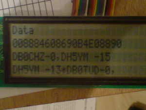
These days i wrote some code to dig into packet radio. I started with some coding to implement KISS (keep it simple and stupid) that was invented in 1987 by KA9Q and K3MC. It is a small protocoll that is similar to the Serial Line Internet Protocoll. It is used to transfer HDLC data over a asyncronous serial interface. KISS adds some capabilities to control some radio parameters for wireless transmissions. At the picture you see the result so far. Data can be received via the serial line. The SLIP decoding is done (removing FEND´s), control parameters are extracted. In addition the path in the header of the transferred AX25 frame is decoded and printed to the display (which is just for understanding all the stuff).
My goal is to design a small KISS/SMACK terminal node controller that can interface a HDLC modem or even do the AX25 frame generation on its own.
Most probably it would be necessary to add some more RAM in order to get enougth frames buffered for transmission. Currently i use a Atmega644 with 4kByte of SRAM. I plan to add external memory to a Atmega8515 but maybe it is cheaper to use one of those new XMEGA´s with 16kByte…
For sure, just for doing some APRS stuff less memory would be sufficient.
New Version of GPS2LCD Software (V1.0)
I continued to hack my AVR software that displays GPS data on a 4×27 character LCD.
Now the software converts all the data into number format and uses this data to write to the display.
The advantage is that you might do some calculations with this data.
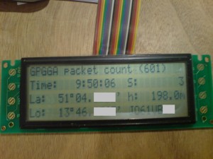
I wrote a routine that calculates the Maidenhead locator. This is now printed to the display as well
including the extended subfield. If Pin PD2 is pulled up the firmware prints all the received data
out to the UART again. For that it is possible to give the data to a existing APRS tracker or to the PC.
So far i saw no data loss at a speed of 4800 baud.
See a picture and find the archive below…
gps2lcd_10
Printing GPS information to LCD
Today i tried to code a small programm that displays information from a GPS receiver on a LCD display. It receives the data via the UART and searches for the GPGGA dataset. If one is received the information (character strings) is written to a 4×27 character HD44780 display. Currently there is no convertion of the data to numbers and no calculations too. A future version might calculate the Maidenhead locator and the distance to a certain coordinate. At my side the programm is running on a Atmega8535 at 16MHz.
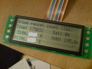
GPS2LCD Version 0.8
UART2LCD
Just for fun i hacked a short program for Atmega that prints all the stuff that comes in at the UART to a 4×27 character LCD. The lines are wrapped automatically. Different baudrates can be selected via 3 input pins. Unfortunately printing to the display is not fast enougth. For that reason characters get lost if you send the complete input for 4 line at once in case a UART speed greater than 19k2 is used.
Future feetures might be:
– improvements to avoid loosing characters from the UART
– adding a mode that cuts lines longer than 27 characters instead of wrapping them
– adding keyboard input possibility
Using a 4 line HD44780 LCD at Atmel controllers
Recently i found a nice C library for AVR controllers that enables to use LCD displays with HD44780
controller connected to the MC. Since i own a 4 line display with 2x HD44780 i wanted to get this
display working too. But two controllers were not supported. At the LCD2USB project sources which use a earlier stage of the libraries from Peter Fleury i found that support for two controllers (which is actually only to handly two enable lines) was hacked in. Since there are some more nice functions i merged the changes necessary to support two halfs of the display to a newer version of the library from Peter.
The result you can find attached. However it comes without warranty ;)

