I was searching for a small driver for 2m in order to have enough power for my microwave transverters. I usually drive them with about 500mW. Since i have a transverter block with about 0dBm output it needs some gain. Again i found something from China. The advertisement told something about 1.5W, the pictures showed a PCB with a print 35dB/3.2W. However, i thought it could be good enough to get 0.5W out of it.
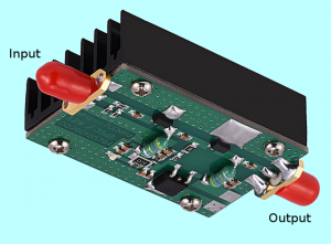
When the device arrived i noticed that the manufacturer milled the top of the two amplifier IC. Very funny that the guys there try to save their designs from unwanted copy ;)
At the input there is a 6dB attenuation pad which are followed by two amplifier stages of unknown type. The first stage is supplied via a 5V regulator, the second one is connected to the supply input directly. I used 12V to do some measurements.
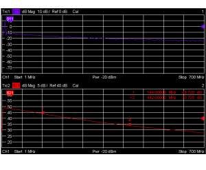
The first action was to know the gain of the circuit. I wanted to see if it is really working from 1 to 700MHz.
In the picture you see the little noisy measurement. The drive from the analyzer was set very low.
From the gain curve it can be seen that the device is probably not working that well at the lowest end of the shortwave. But at least from 30MHz on it should be usable. Towards upper frequencies the gain is decreasing a lot but still 27dB at 700MHz. For the 2m band roughly 43dB gain is achieved and about 33dB in the 70cm band.
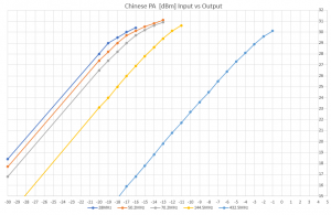
Finally i wanted to know which output power can be achieved in the amateur radio bands.
At about 1W output the output always gets compressed. You might add about 0.4dB on 70cm and 0.3dB on 2m to my measurements since the graph does not include the attenuation of the output cable. For me it means that the amplifier should work well for my purpose.


